▶ Maintenance
c1 setup video
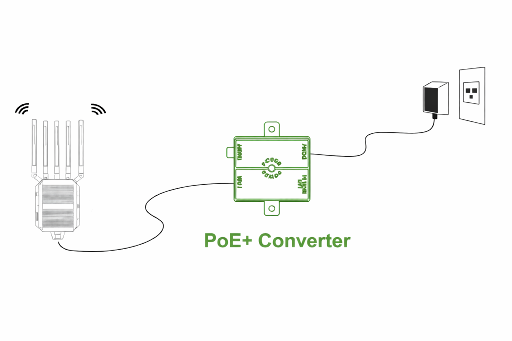
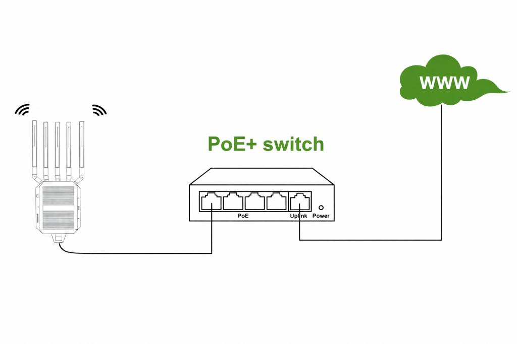
| Via POE+ Converter | Via POE+ Switch |
|
|
| 30W/48V/0.6A POE+ Converter | 30W/48V/0.6A POE+ Switch |
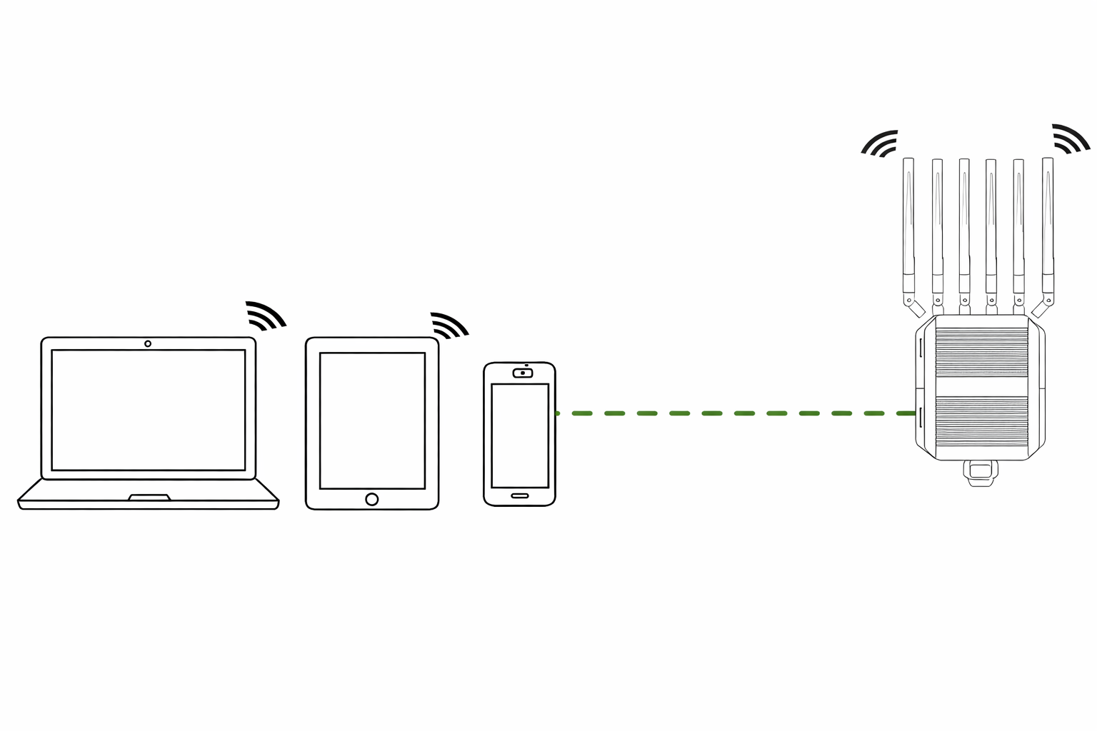
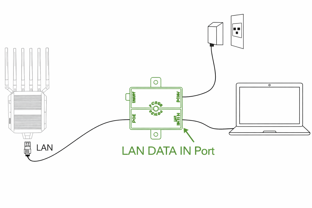
| Via Wi-Fi | Via Cable |
|
|
|
To connect to the C1 and get access to the router settings please follow these steps:
To add a SIM Card to the olixLink™ C1 follow these steps
ping 8.8.8.88.8.8.8video c1 simcard
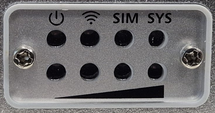
| LED | Status | Description |
|---|---|---|
| Power LED | ||
| Green | Stable green | Power on |
| Gray | Off | Power off |
| SIM card LED | ||
| Green | Stable green | SIM card is recognized |
| Gray | Off | SIM card not inserted nor recognized |
| RF LED | ||
| Green | Stable Green (From 1 to 4 LEDs) | Shows 5G signal strength (1 poor – 4 very strong) |
| Gray | Off | Signal not available |
| System LED | ||
| Green | Flashing green | System running |
| Gray | Off | System not running |
| WiFi LED | ||
| Green | Stable green | WiFi is working |
| Gray | Off | WiFi not started |
The OlixLink™ C1 device provides its own ROS 2 node that publishes a status topic to report the current state of the unit. Once the connection to the router is established, the node publishes to the topic: /olive/olixLink/c1/id001/statuswith the message type diagnostic_msgs/msg/DiagnosticArray
This node is natively integrated with Eclipse Cyclone DDS, but the status topic remains discoverable and accessible even if the host system is using a different DDS implementation.
Since by default the LAN is selected by cyclone as primary ROS 2 network. You will mostlikely not see the status topic. But you can change the interface by a config. Following config is an example config to select right network
<?xml version="1.0" encoding="UTF-8" ?>
<CycloneDDS xmlns="https://cdds.io/config"
            xmlns:xsi="http://www.w3.org/2001/XMLSchema-instance"
            xsi:schemaLocation="https://cdds.io/config https://raw.githubusercontent.com/eclipse-cyclonedds/cyclonedds/master/etc/cyclonedds.xsd">
    <Domain Id="any">
        <General>
            <Interfaces>
                 <!-- Please select your interface name which is connected
                      with the OlixLink C1 -->
                <NetworkInterface name="wlp8s0"/>
            </Interfaces>
            <AllowMulticast>true</AllowMulticast>
        </General>
    </Domain>
</CycloneDDS>
Then set the configs
ros2 daemon stop
export CYCLONEDDS_URI=file:///path/to/cyclone_c1.xml
ros2 daemon start
The Status message contains following information:
| Value | Description |
|---|---|
| ESSID | The WiFi name |
| Frequency | The frequency of the WiFi |
| Signal level | How good is the signal of the WiFi in dBm |
| Received data | Received data in bytes per second |
| Transmitted data | Received data in bytes per second |
| Value | Description |
|---|---|
| Total Memory | Total memory in kB |
| Used memory | Used memory in kB |
| Remaining memory | free memory in kB |
| Value | Description |
|---|---|
| Status | Sim Card is available or not, Values: UP | DOWN |
| Received data | Received data in bytes per second |
| Transmitted data | Received data in bytes per second |
An IP address can be configured through the ROS 2 parameters. Once set, the OlixLink™ C1 status node will periodically measure and report the latency between the device and the specified IP address, providing valuable network performance insights as part of its diagnostic data.
| Value | Description |
|---|---|
| IP Address | Shows the chosen IP address |
| Latency | Latency in ms |
The ROS 2 Configuration can be changed via Web GUI.
ros2 configs v2 c1 video
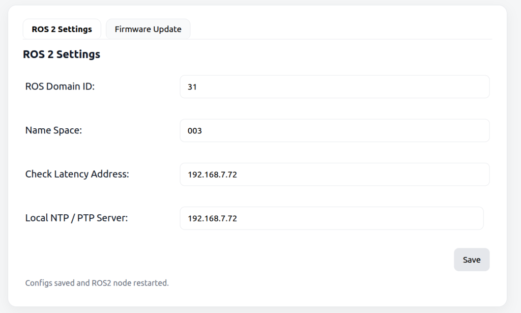
Here is a more detailed description of those parameters
| Value | Description |
|---|---|
| ROS Domain ID | Change the ROS domain ID of the router |
| Name Space | Change the Name Space of the C1 status topic |
| Check Latency Address | Add an IP address to check the latency |
| Local NTP / PTP Server | Add IP address of an ntp server to sync the C1 time with your host system time |
To update the firmware of the olixLink™ C1 follow these steps:
firmware_update_v2 video
In this section, the individual tabs of the web interface are explained.