¶ 4 Software Development
This section provides an overview of important technical details that may be required during software development with the robot.
It introduces relevant system components, interfaces, and configuration aspects that developers may need when integrating custom applications, modifying existing functionalities, or extending the robot’s capabilities. Topics such as ROS 2 interfaces, communication mechanisms, simulation workflows, and system architecture are covered to support efficient development and debugging.
This section is intended for users who wish to go beyond standard operation and develop custom software solutions based on the robot platform.
¶ 4.1 Overview
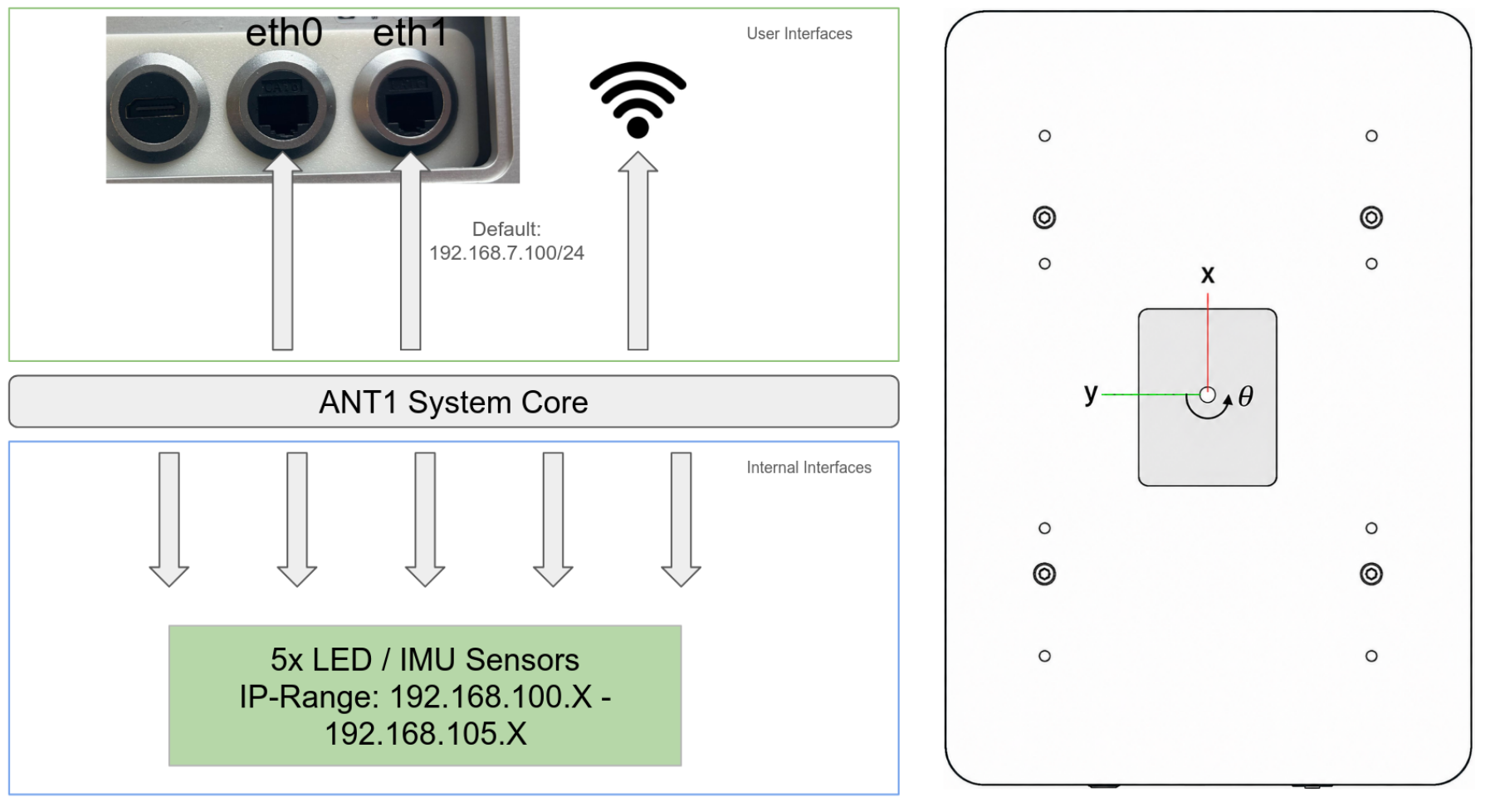
This section gives an overview of the available network interfaces and the available coordinate frames.
The eth1 interface has a default address of 192.168.7.100/24 which makes it available to access the robot and to setup the other network interfaces.
Connect to WIFI
To enable wireless access to ANT1, it can be configured to act as a client on a Wi-Fi network. The video below shows how to connect ANT1 to a Wi-Fi network.
|
|
¶ 4.2 ROS2 API
This section describes the ROS 2 interfaces provided by the robot for communication, control, and data exchange. It introduces the available topics, services, and actions that can be used to interact with the system programmatically.
¶ Topics
All of them has a default namespace of /olive/olixRobot/ant1/id001/
| Topic name | Format | Type | Function |
| status | diagnostic_msgs/msg/DiagnosticStatus | subscriber | ANT1 status information |
| battery | std_msgs/msg/Int32 | subscriber | Battery status information in percentage |
| system_voltage | std_msgs/msg/Float32 | subscriber | Voltage of the Battery |
| ems | std_msgs/msg/Bool | subscriber | Emergency stop status, True indicates emergency stop active. |
| tf | tf2_msgs/msg/TFMessage | subscriber | Transform data between coordinate frames |
| cmd_vel | geometry_msgs/Twist | subscriber | Velocity commands (linear and angular) for controlling the robot’s motion. This is the primary interface for external velocity control. |
| joy | sensor_msgs/msg/Joy | subscriber | Joystick input data, including axis values and button states, for manual control or mode switching |
| odom | nav_msgs/msg/Odometry | subscriber | Fused Odometry of different inputs (e.g. scan, wheel, imu). This odom topic is used for navigation |
| wheel_odom | nav_msgs/msg/Odometry | subscriber | Wheel odometry data, including estimated position, orientation, and velocity. |
| wheel_rpm | std_msgs/msg/Float32MultiArray | subscriber | Wheel speed values in RPM |
| image/compressed | sensor_msgs/msg/CompressedImage | subscriber | Camera Topic (only available a Ultra Version) |
| image/camera_info | sensor_msgs/msg/CameraInfo | subscriber | Camera Info Topic: Shows calibration values of the Camera (only available at Ultra Version) |
¶ LED and Imu Topics
In ANT1 there are in total 5 LEDs with an IMU inside (olixSense™ S1), each of them has this 4 topics (except the bottom middle one the LED can not be changed). The naming are based on their position on ANT1:
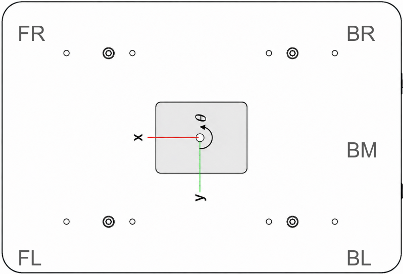
This table shows an example of the BL LED Topics. Replace the bl with e.g. fl and you get the front-left LED.
| Topics | Format | Type | Function |
| s1/bl/diagnostics | diagnostic_msgs/msg/DiagnosticArray | subscriber | Get diagnostic info of olixSense™ S1 |
| s1/bl/imu | sensor_msgs/msg/Imu | subscriber | Get the IMU data |
| s1/bl/led_rgb | std_msgs/msg/Float32MultiArray | subscriber | Get the current LED Value |
| s1/bl/user/led_rgb | std_msgs/msg/Float32MultiArray | publisher | Change the LED Color by the data array (Values are RGB format but normalized (0 - 1)) |
Example of changing the BL-LED to red:
ros2 topic pub /olive/olixRobot/ant1/id001/s1/bl/user/led_rgb std_msgs/msg/Float32MultiArray "layout:
  dim: []
  data_offset: 0
data: [1.0, 0.0, 0.0]"¶ Scan Topics
Similar to the LED and IMU topics, there are four laser scan topics. They follow the same naming convention shown in the image above. In addition, there is a fused scan topic that combines the data from all four laser scanners.
The XX placeholder can be replaced with the corresponding corner abbreviation. For example, for the bottom-left laser scanner, XX is replaced with bl.
| Topics | Format | Type | Function |
| scan_XX | sensor_msgs/msg/LaserScan | subscriber | Scan topic of each corner |
| scan_XX_status | diagnostic_msgs/msg/DiagnosticArray | subscriber | Status of the Scanner |
| scan | sensor_msgs/msg/LaserScan | subscriber | Fused scan topic of all 4 Laser scanner |
Each laser is managed by a ROS 2 lifecycle node, which allows it to be enabled or disabled at runtime. When a laser is disabled, its data is no longer included in the fused laser scan. The current state of each laser can be checked via its status topic or in the Web UI (see the Web UI chapter).
This video shows the process of how to activate and deactivate the laser scanners
|
|
In some cases, lifecycle transitions may be slow or become unresponsive, for example due to network issues. As an alternative, laser scanners can also be activated or deactivated directly using a ROS 2 service call.
ros2 service call /olive/olixRobot/ant1/id001/STL27L_bl/change_state lifecycle_msgs/srv/ChangeState "transition: id: 4 label: ''"The
idvalue indicates the scanner state:id = 4means the laser scanner is deactivated, whileid = 3means it is activated.
For more information about the ros2 lifecycle node check following site
Warning: In some cases, the laser scanners may not be available after startup because too many devices draw power simultaneously. To prevent this, keep the emergency stop button engaged during startup. After approximately 10 seconds, release the emergency stop button. This should prevent the issue.
¶ Safety Distance
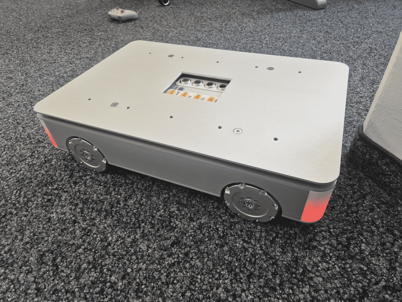
By default, ANT1 uses the laser scanners to maintain a safety distance around the robot. If an obstacle enters this safety zone, the robot immediately stops moving and remains stopped until the obstacle leaves the area. While the robot is stopped for safety reasons, the corner LEDs indicate this state by lighting up orange.
The safety distance can be adjusted at runtime using the ROS 2 parameter laser_safety_distance_cm on the /olive_olixRobot_id001_ant1 node.
# Get the current distance
ros2 param get /olive_olixRobot_id001_ant1 laser_safety_distance_cm
Output: Integer value is: 17

# Change the distance
ros2 param set /olive_olixRobot_id001_ant1 laser_safety_distance_cm 16
Output: Set parameter successful: success The laser safety feature can also be enabled or disabled using a ROS 2 service call or a key combination on the controller.
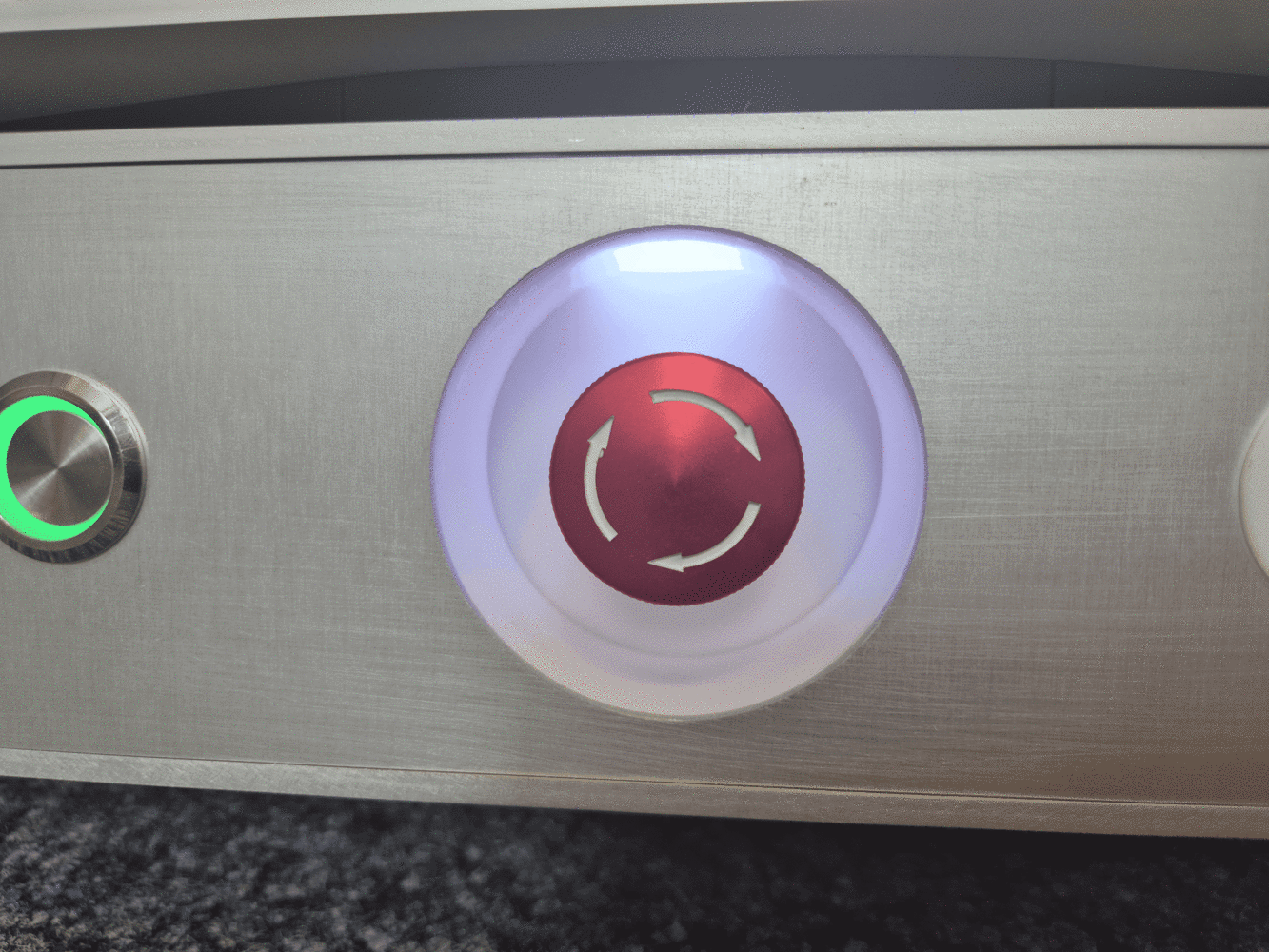
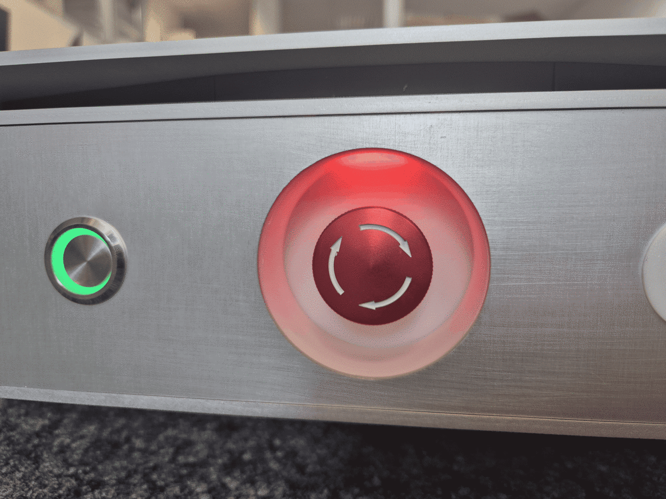
The current state of the feature is indicated by the Emergency Stop LED:
- Orange: Laser safety is disabled.
- White: Laser safety is enabled.
|
|
Via Service:
# Disable
ros2 service call /olive/olixRobot/ant1/id001/laser_safety/enable std_srvs/srv/SetBool "data: false"   # Emergency Stop Led turns orange

# Enable
ros2 service call /olive/olixRobot/ant1/id001/laser_safety/enable std_srvs/srv/SetBool "data: true" # Emergency Stop Led turns whiteVia Controller:
Press the Buttons LB + X for three seconds to switch the modes, the led will indicate in which mode ANT 1 is.
Hint: The Safety Distance mode is re-enabled on each restart.
¶ Services
All of them has a default namespace of /olive/olixRobot/ant1/id001/
| Topics | Format | Function |
| reboot | std_srvs/srv/Trigger | Reboot the System |
| reset_wheel_odom | std_srvs/srv/Trigger | Reset Wheel Odom |
| restartDCMServices | std_srvs/srv/Trigger | Restart the DCM Service |
¶ Robot Controlling
To control the robot two following ways are possible.
- Manual Mode via controller. Follow this steps
- Via ROS Nav2 Stack. See Navigation Section
- Via ROS2 API:
You can publish to the cmd_vel topic the velocity and choose which direction. Since the robot can only move in X and Y linear and turn on the yaw axis, an Input could look like that:
ros2 topic pub /cmd_vel geometry_msgs/msg/Twist "linear:
  x: 0.1
  y: 0.1
  z: 0.0
angular:
  x: 0.0
  y: 0.0
z: 2.0" Based on example above ANT1 drives 0.1 m/s in x and y direction and turns with 2 m/s
¶ 4.3 Navigation
With ANT1 Pro and Ultra you can drive your system autonomously via Nav2. There a two different modes mapping and navigation
¶ Mapping
In the mapping mode you can create a map which later can be used in the navigation. To start the mapping go to the Web-UI under SLAM and in the Robot Control Section select Mapping and start mapping. The video below shows you how to create a map using the Web-UI.
|
|
Network traffic for visualization data is intentionally limited. As a result, mapping in the Web UI may appear delayed or less responsive. Since the Web UI is primarily intended for monitoring and visualization, the amount of data transmitted to it is restricted to reduce network traffic.
For a more responsive and reliable real-time visualization, use RViz2 on your host system, as shown in the video.
You can download a ready to use rviz config via this git repo and run it with following command:
ros2 run rviz2 rviz2 -d g1_slam.rviz --ros-args -r __node:=rviz -r __ns:=/olive/olixRobot/ant1/id001 -r /initialpose:=initialpose -r /goal_pose:=goal_pose -r /navigate_to_pose:=navigate_to_pose -r /navigate_through_poses:=navigate_through_posesYou need to remap all of these topics, since rviz does not respect the namespace, this can also be done via a launch file
¶ Navigation & Waypoints
|
|
Network traffic for visualization data is intentionally limited. As a result, navigation in the Web UI may appear delayed or less responsive. Since the Web UI is primarily intended for monitoring and visualization, the amount of data transmitted to it is restricted to reduce network traffic.
For a more responsive and reliable real-time visualization, use RViz2 on your host system, as shown in the video.
You can download a ready to use rviz config via this git repo and run it with following command:
ros2 run rviz2 rviz2 -d g1_navigation.rviz --ros-args -r __node:=rviz -r __ns:=/olive/olixRobot/ant1/id001 -r /initialpose:=initialpose -r /goal_pose:=goal_pose -r /navigate_to_pose:=navigate_to_pose -r /navigate_through_poses:=navigate_through_posesYou need to remap all of these topics, since rviz does not respect the namespace, this can also be done via a launch file
The Web UI sometimes has caching issues. If this happens, refresh the topics by clicking the Topic dropdown, as shown in the video.
Waypoint Services
Waypoints are defines points in the map which can be then selected by name and ANT1 drives to this predefined points. You can use our own written waypoints node which is described below and also works via the WEB-UI or you can use the already built-in NavigateToPose from Nav2.
Waypoint can be edited over the Web-UI like shown at the video above and also via ros2 CLI with services:
The interfaces need to be installed first by building the interfaces from this repo
All of them has a default namespace of /olive/olixRobot/ant1/id001/
| Service name | Format | Function |
| waypoint_server/delete_waypoint | waypoint_server_interfaces/srv/DeleteWaypoint | Deletes the specified waypoint from the waypoint database. If the waypoint does not exist, the request will fail. |
| waypoint_server/list_waypoints | waypoint_server_interfaces/srv/ListWaypoints | Returns a list of all currently stored waypoint names. |
| waypoint_server/move_to_waypoint | waypoint_server_interfaces/srv/MoveToWaypoint | Commands the robot to navigate to the waypoint identified by the given name. The waypoint must exist and the navigation stack must be active. |
| waypoint_server/save_waypoint | waypoint_server_interfaces/srv/SaveWaypoint | Saves the robot’s current base position (in the map frame) as a waypoint with the specified name. |
| waypoint_server/save_waypoint_pose | waypoint_server_interfaces/srv/SaveWaypointPose | Saves a waypoint with a user-defined pose in the map frame. The pose must be provided in map coordinates. |
- Here are the examples:
# Save current robot position as a waypoint
ros2 service call /waypoint_server/save_waypoint \
  waypoint_server_interfaces/srv/SaveWaypoint \
"{name: 'wp_1'}" |
|
# Save a custom pose as waypoint
ros2 service call /waypoint_server/save_waypoint_pose \
  waypoint_server_interfaces/srv/SaveWaypointPose \
  "name: 'wp_custom'
pose:
  position:
    x: 2.0
    y: 1.0
    z: 0.0
  orientation:
    x: 0.0
    y: 0.0
    z: 0.0
    w: 1.0"
|
|
# List all saved waypoints
ros2 service call /waypoint_server/list_waypoints \
  waypoint_server_interfaces/srv/ListWaypoints \
"{}" |
|
# Navigate to a saved waypoint
ros2 service call /waypoint_server/move_to_waypoint \
  waypoint_server_interfaces/srv/MoveToWaypoint \
"{name: 'wp_1'}" |
|
# Delete a waypoint
ros2 service call /waypoint_server/delete_waypoint \
  waypoint_server_interfaces/srv/DeleteWaypoint \
  "{name: 'wp_1'}"
|
|
¶ 4.4 ROS2 Tools
¶ RVIZ2
RVIZ2 is a powerful 3D visualisation tools, whRViz2 is a powerful 3D visualization tool used within the ROS 2 ecosystem. It provides real-time insight into the robot’s state, sensor data, and navigation behavior while the system is operating.
With RViz2, users can:
- Visualize LiDAR scans and point clouds
- Monitor the robot’s pose and TF coordinate frames
- Display maps generated by SLAM
- Observe planned navigation paths
- Send navigation goals (e.g., 2D Nav Goal / Nav2 Goal)
- Initialize the robot’s pose using the 2D Pose Estimate tool
RViz2 is an essential tool during development, testing, and debugging. It allows users to verify that sensor data aligns correctly with the map, confirm that localization is stable, and ensure that navigation planning behaves as expected.
Preconfigured RViz2 layouts are provided with the ANT1 repository to simplify setup and reduce manual configuration. These configs can be found here
To use the buttons like Set Inital Pose etc it is necessary to remap the topics that it adapts to the right namespace for example
ros2 run rviz2 rviz2 -d g1_navigation.rviz --ros-args
-r __node:=rviz  -r __ns:=/olive/olixRobot/ant1/id001 -r /initialpose:=initialpose
-r /goal_pose:=goal_pose -r /navigate_to_pose:=navigate_to_pose -r /navigate_through_poses:=navigate_through_poses¶ Gazebo
The ANT1 platform is supported by a Gazebo-based simulation environment. This environment allows users to test functionalities, validate algorithms, and simulate realistic operational scenarios without requiring physical hardware.
A comprehensive introduction to the simulation setup, configuration, and usage is provided in Chapter 4: Simulation.
¶ 4.5 WebUI
The ANT1 will provide an optional WebUI to simplify day-to-day operation and configuration. The WebUI is designed for user-friendly access to common settings without requiring direct ROS 2 commands.
With the WebUI, users will be able to:
- Adjust key parameters (e.g., navigation and control settings)
- Enable or disable supported features
- Monitor robot status and basic system information
- Perform basic control and operation tasks
¶ Robot Dashboard
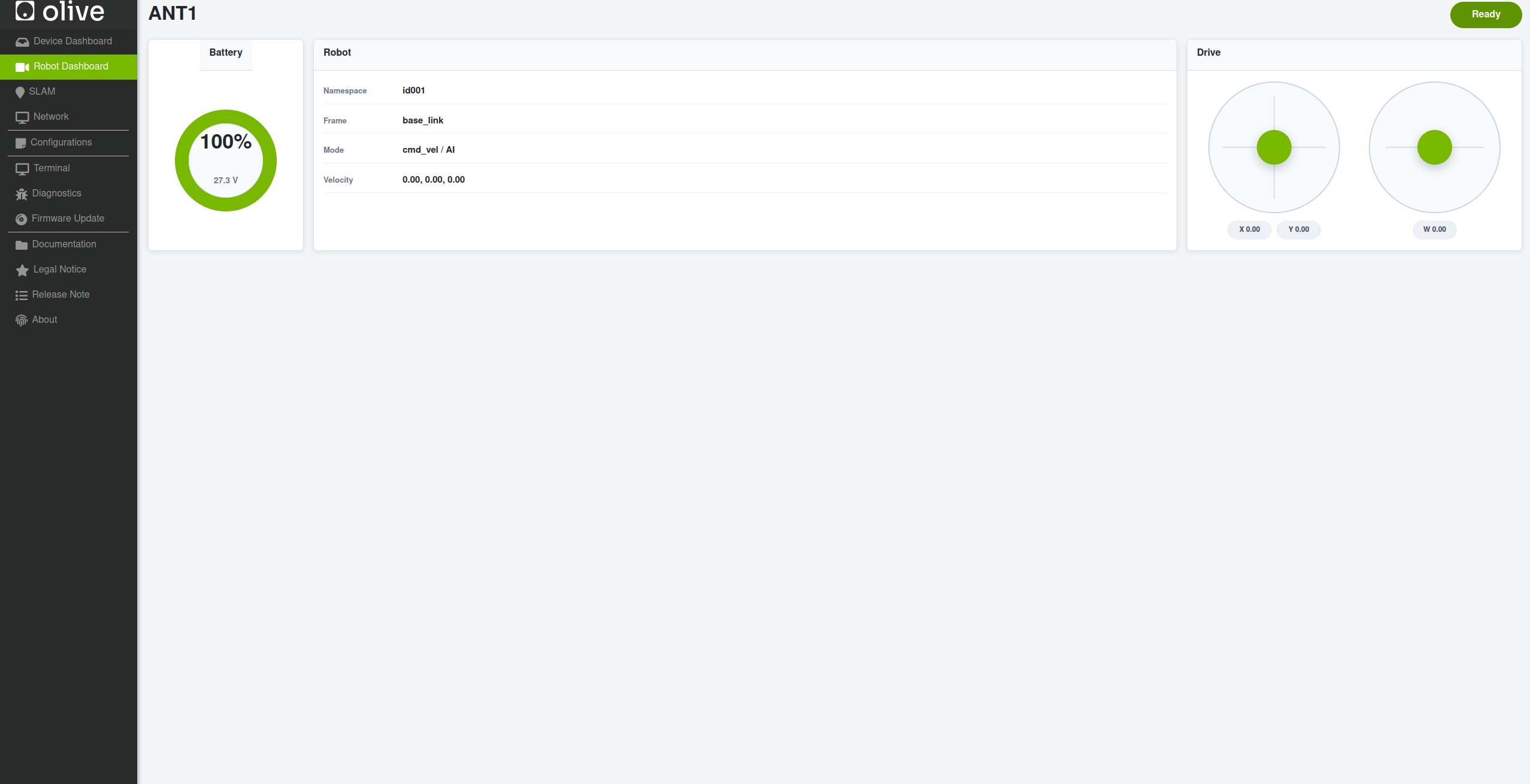
| Name | Description |
|---|---|
| Battery | Displays battery percentage and current voltage. In the screenshot, the battery is at 100% / 27.3 V. |
| Robot | Provides an overview of the robot’s namespace, frame, control mode, and current velocity. |
| Drive | Contains joystick-style controls for manually moving and rotating the robot. |
¶ SLAM Dashboard
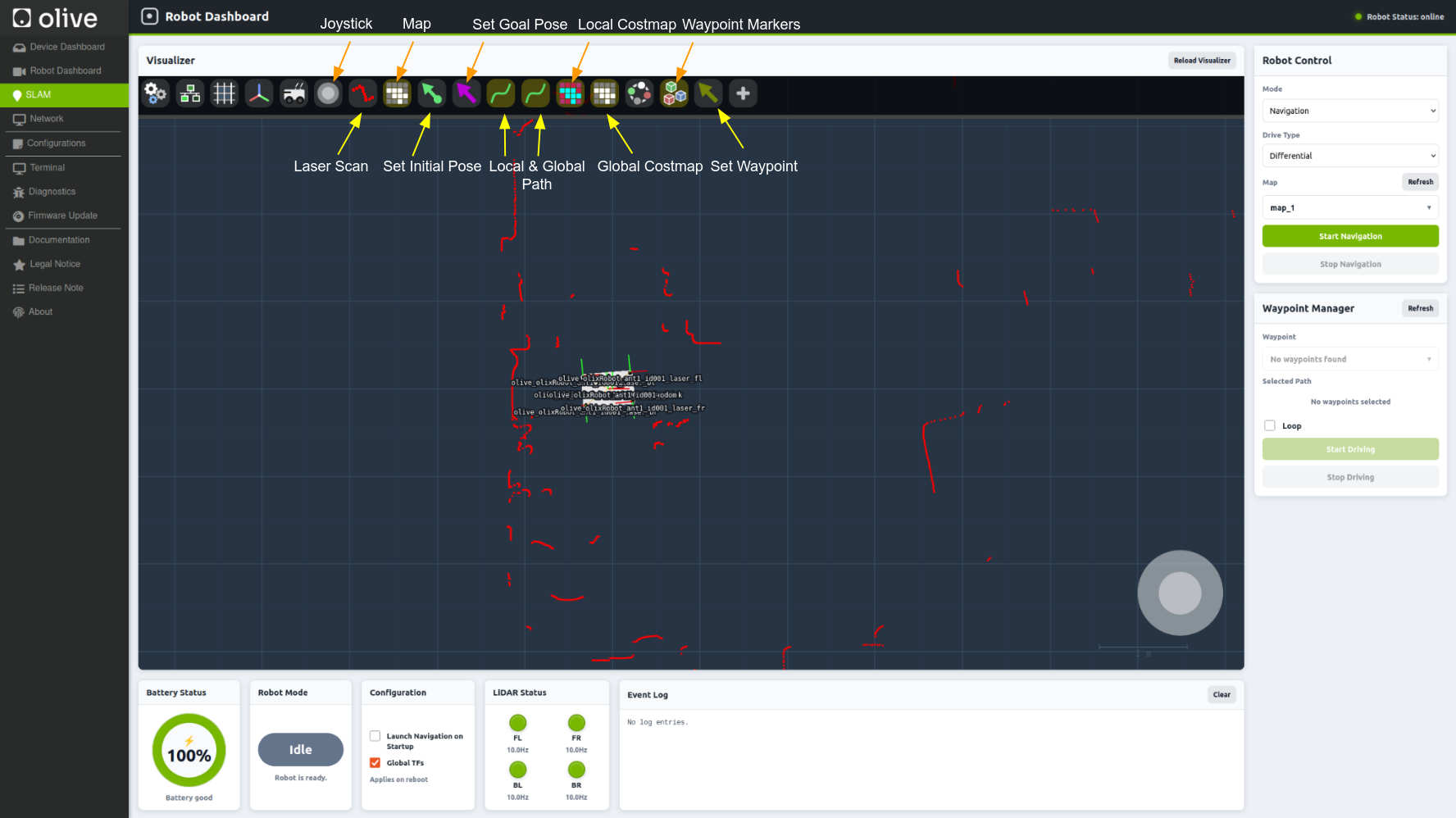
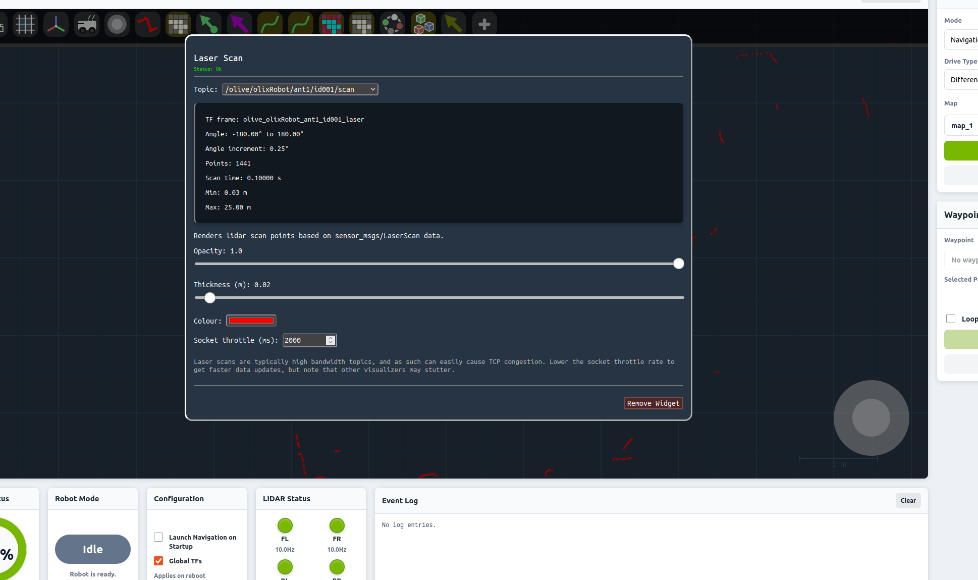
Description of the shown parts. Please checkout the Mapping and Navigation Video to see how to use the SLAM Dashboard
¶ Visualizer part
| Name | Description |
|---|---|
| Joystick | Opens the joystick control for manually driving the robot. |
| Map | Shows or hides the currently loaded map in the visualizer. |
| Set Goal Pose | Lets you select a target position and orientation for the robot to navigate to. |
| Local Costmap | Displays the local costmap around the robot, including nearby obstacles and navigation costs. |
| Waypoint Markers | Shows the waypoint markers that have been created on the map. |
| Laser Scan | Displays the live LiDAR / laser scan points detected around the robot. |
| Set Initial Pose | Sets the robot's estimated starting position and orientation on the map. |
| Local & Global Path | Shows the planned navigation paths. The global path represents the overall route, while the local path shows the robot's short-term path. |
| Global Costmap | Displays the global navigation costmap, including obstacles and areas the planner should avoid. |
| Set Waypoint | Lets you place a waypoint at a selected position on the map. |
¶ Cards Description
| Name | Description |
|---|---|
| Robot Control | Contains the main navigation and mapping controls, including mode, drive type, map selection, and Start/Stop Navigation. (See Navigation chapter for a tutorial) |
| Waypoint Manager | Used to select waypoints, create a waypoint path, enable looping, and start or stop waypoint driving. |
| Battery Status | Shows the robot's current battery percentage and battery condition. |
| Robot Mode | Displays the robot's current operating state, such as Idle. |
| Configuration |
Contains navigation-related settings that can be enabled or disabled. Launch Navigation on Startup: If enabled it will launch the last pose and the last map which was used on startup Global TFs: Choose wheteter TF and TF_Static will be as a global parameter or namespaced
|
| LiDAR Status | Shows the status and update frequency of the individual LiDAR sensors. |
| Event Log | Displays navigation, robot, or system events and messages during operation. |
¶ Configuration Dashboard
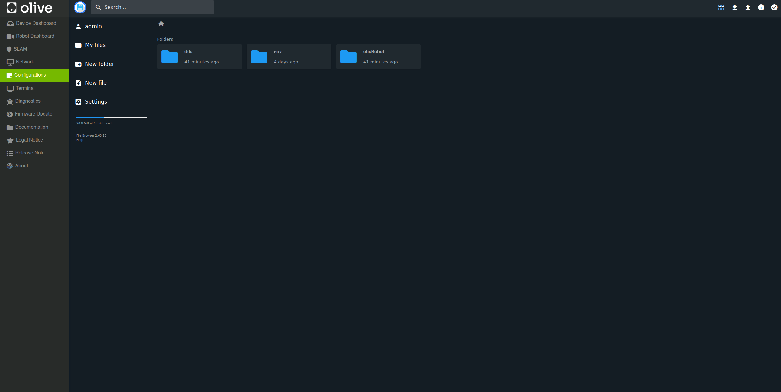
In the config dashboard you can change different parameters like the cyclone config under dds/cyclonedds.xml or the navigation parameters for omnidirectional or differential driving style of ANT1.
These parameters you can find under olixRobot/nav_params. You can find the definition of each parameter in the nav2 documentation
Warning: Please be aware that changing parameters can affect the entire system and may damage the robot.
¶ 4.6 Fleet Management System
¶ 4.7 Camera (Ultra Version)
The Camera contains two topics:
- /olive/olixRobot/ant1/id001/image/camera_info
- /olive/olixRobot/ant1/id001/image/compressed
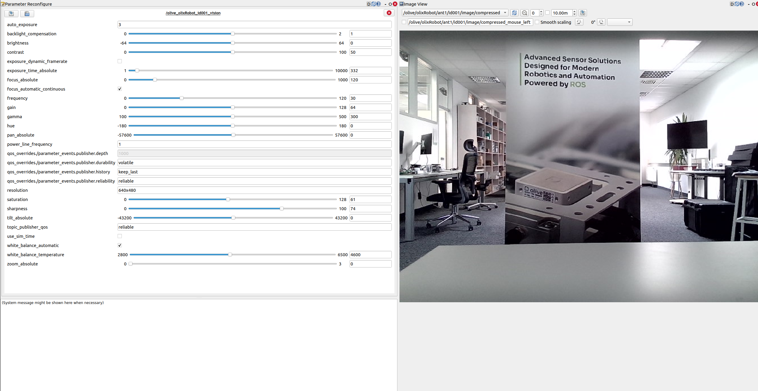
The first one shows the camera info like intrinsic camera matrix etc and the second one the image.
It also contains different configurations which can be changed with the ros2 parameters or RQT. Below you can see the possible configurations of this camera and the image itself.
It is recommended to use the camera only with systems that are directly connected to the robot via a wired network connection. DDS in general, and Cyclone DDS in particular, may not perform reliably over Wi-Fi when handling this amount of data.
If a Wi-Fi connection is required, it may help to adjust the Cyclone DDS configuration, for example by using explicitly defined peers or by using the spdp protocol in the AllowMulticast setting since this forces cyclone to just do the participant discovery over multicast but sending data over unicast.
<AllowMulticast>spdp</AllowMulticast>Refer to the Cyclone DDS documentation for further information on the available configuration options.