¶ Overview
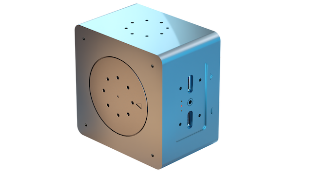
The olive® Servo is the easiest way to get your robotic system moving. This high-performance robotics component is designed for a wide range of applications. It is re-programmable and easy to integrate, making it simple for users to build custom robots and automated systems. The actuator has a plug-and-play design for quick setup, and it is compatible with multiple robotic operating systems, giving users flexibility in software tooling.
¶ Key Features
- ROS and ROS2 out of the box. No setup required.
- High-torque motor: The olive® Servo module features a high-torque motor that provides the power and torque needed to move heavy loads or to perform high-precision tasks.
- Easy integration: The olive® Servo is designed to be easy to integrate into a variety of different robotic systems. It just works through plug and play.
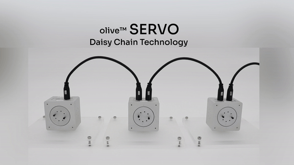
- Daisy-chainable: Extend your system’s functionality by plugging additional hardware into the olive® Servo’s input port: either another olive® hardware component or a USB-C peripheral.
- Various control modes: olive® Servo offers five different modes of control: raw control (pwm), position control, velocity control, trajectory control and wheel mode control.
- Software-defined: The olive® Servo is software-defined, allowing users to customize its communication layer, behaviour, and functionality through software rather than hardware.
- Auto-voltage: the olive® Servo can run in different voltage modes: 5 / 9 / 12V. The specific voltage is automatically adjusted to the power intake to ensure maximum performance in all conditions.
¶ Demo
¶ olive® Servo Models
The olive series of servos includes four different models that are distinguished by their rotations per minute (RPM). Each servo comes with with an on-board 9D high-performance IMU. These are the available options:
| Name | Type | Sensors | Max Data Rate | RPM | Information |
|---|---|---|---|---|---|
| OLV-SRV01-S16 | Servo + IMU | Rotary Position Sensor & IMU Sensor (9D) | 40000Hz / 100 Hz | 16 | High Torque Servo Motor & IMU |
| OLV-SRV01-S32 | Servo + IMU | Rotary Position Sensor & IMU Sensor (9D) | 40000Hz / 100 Hz | 32 | Mid Torque Servo Motor & IMU |
| OLV-SRV01-S48 | Servo + IMU | Rotary Position Sensor & IMU Sensor (9D) | 40000Hz / 100 Hz | 48 | Mid RPM Servo Motor & IMU |
| OLV-SRV01-S64 | Servo + IMU | Rotary Position Sensor & IMU Sensor (9D) | 40000Hz / 100 Hz | 64 | High RPM Servo Motor & IMU |
¶ Olive® Operational Modes
To change the servo mode you can open the debug gui and select the servo’s mode:
¶ 1. PWM Control
Description: Pulse Width Modulation (PWM) control is a technique used to regulate the power supplied to electrical devices, such as actuators. It adjusts the duty cycle of the input signal, controlling the amount of power provided to the actuator.
- Input: Duty cycle (-1 to 1)
- Output: Power supplied to the actuator
- Subscriber topic: /olive/servo/name_space/pwm
¶ 2. Position Control
Description: Position control is used to maintain or adjust the position of an actuator. The controller computes the difference between the desired and actual positions and adjusts the actuator accordingly.
- Input: Desired position
- Output: Actual position of the actuator
- Subscriber topic: /olive/servo/name_space/goal/position
- PID: A PID controller is used to minimize the position error, adjusting the control signal to change the actuator’s position.
¶ 3. Velocity Control
Description: Velocity control is used to maintain or adjust the velocity of an actuator. The controller computes the difference between the desired and actual velocities and adjusts the actuator accordingly.
- Input: Desired velocity
- Output: Actual velocity of the actuator
- Subscriber topic: /olive/servo/name_space/goal/velocity
- PID: A PID controller is used to minimize the velocity error, adjusting the control signal to change the actuator’s velocity.
¶ 4. Trajectory Control
Description: This mode controls the position of the actuator, like position control does. But it does something extra: it uses a jitter buffer to give the PID controller a steady stream of data at regular intervals. This is especially useful when you’re sending position targets over a network where timing isn’t guaranteed. It’s also great for situations where following the trajectory smoothly matters more than how fast it’s executed.
- Input: Desired position
- Output: Actual position of the actuator
- Subscriber topic: /olive/servo/name_space/goal/position
- PID: A PID controller is used to minimize the position error, adjusting the control signal to change the actuator’s position.
¶ 5. Wheel Control
Description: It operates similarly to velocity control but incorporates a watchdog mechanism designed to swiftly halt the motor if velocity commands fail to arrive within an assured interval. This feature is particularly valuable in wheel mode control scenarios, where preventing the robot from unintended movement due to high-level logic crashes or network issues is essential.
- Input: Desired velocity
- Output: Actual velocity of the actuator
- Subscriber topic: /olive/servo/name_space/goal/velocity
- PID: A PID controller is used to minimize the velocity error, adjusting the control signal to change the actuator’s velocity.
¶ Technical Specifications
| Part Number | OLV-SRV01-S* |
|---|---|
| Connection Interface | USB Type-C |
| Communication | USB Type C – Ethernet Over USB |
| Communication Protocol | ROS 1&2 (Virtual Ethernet / IPV4) |
| Rotations per Minute | 16 / 32 / 48 / 64 |
| Motor Control Pulse Duration | 1000kHz |
| Rotaray Position Resolution | 16384 |
| IMU Sample rate | 100 Hz |
| Gyroscope range | +/- 2000 deg/sec |
| Accelerometer range | +/- 16 g |
| Magnetometer range | +/- 4 gauss |
| Gyroscope accuracy | +/- 0.05 deg/sec |
| Accelerometer accuracy | +/- 0.1 g |
| Magnetometer accuracy | +/- 0.2 gauss |
| Performance Metrics | Covariance Matrix |
| Operating Voltage | 5.0V / 9.0V / 12.0V (auto adjusted) |
| Voltage Read Resolution | 65536 |
| Weight | 180 grams |
| Dimensions WxHxD | 60x60x46 mm |
| Native ROS Messages | sensor_msgs/JointState, sensor_msgs/Imu*, sensor_msgs/Temperature |
| Operating Temperature | 0 ~ 55 °C |
¶ Quick Setup
- Follow the Quick Start Guide for Olive Robotics robot modules to connect the device and start using it.
- When the servo is correctly connected to your system, you can check that the expected ROS topics are present. On your host PC, run
ros2 topic list. The following ROS topics should be shown:/olive/servo/id001/pwm/olive/servo/id001/magnet/angle/olive/servo/id001/magnet/moving_average/olive/servo/id001/magnet/auto_gain/olive/servo/id001/magnet/magnitude/olive/servo/id001/magnet/diagnostic/olive/servo/id001/joint/olive/servo/id001/joint/voltage/parameter_events/rosout
The number id001 is your device’s default namespace.
- Change the parameters like IP, ROS topic name, etc. using the embedded web interface.
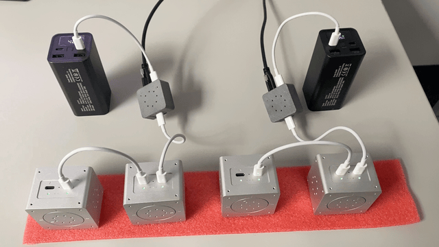
¶ Voltage Splitter for PD motors
If your motor is PD-enabled, it offers compatibility with both 12V batteries and external power sources. Activating the PD mode requires using the splitter and connecting the data and power cables as illustrated in the accompanying image:
¶ Daisy Chain with Voltage Splitter
¶ ROS Topics and Services
¶ PWM Control Mode (Base topics)
| Topic Name | Message Type | Type | Description |
|---|---|---|---|
| …/pwm | std_msgs/Float32 | Subscriber | Control the raw pwm control value. -1.0 to 1.0 |
| …/magnet/angle | std_msgs/Float64 | Publisher | Current angular position of the servo. [radian] |
| …/magnet/moving_average | std_msgs/Float64 | Publisher | Moving average of .../magnet/angle [radian] |
| …/magnet/auto_gain | std_msgs/Byte | Publisher | The rotary sensor’s auto gain register. |
| …/magnet/magnitude | std_msgs/Float64 | Publisher | The rotary sensor’s magnitude register. |
| …/magnet/diagnostic | std_msgs/String | Publisher | The rotary sensor’s diagnostic status. |
| …/joint | sensor_msgs/JointState | Publisher | The servo current joint state. |
| …/joint/voltage | std_msgs/Float64MultiArray | Publisher | The servo current joint state. |
¶ Position Control Mode (Additional topics)
| Topic Name | Message Type | Type | Description |
|---|---|---|---|
| …/goal/position | std_msgs/Float32 | Subscriber | Desired position |
¶ Velocity Control Mode (Additional topics)
| Topic Name | Message Type | Type | Description |
|---|---|---|---|
| …/goal/velocity | std_msgs/Float32 | Subscriber | Desired velocity |
¶ Services
| Service Name | Type | Description |
|---|---|---|
| …/setZero | std_srvs/Trigger | Redefine the servo’s current position to be zero. |
| …/setTorqueEnable | std_srvs/Trigger | Enables the servo torque. |
| …/setTorqueDisable | std_srvs/Trigger | Disables the servo torque. |
¶ Advanced Settings
The device allows certain parameters to be changed at runtime. To get an overview of all changeable parameters use ros2 param list. To change a parameter use ros2 param set /dcm_actuator <parameter> <new_value>
¶ Servo
¶ PWM Control Mode (Base params)
| Parameter | Type | Range Min | Range Max | Default | Description |
|---|---|---|---|---|---|
| frequency | int | 0 | 1000 | 100 | Actuator status publish rate |
| lpf_velocity_gain | double | 0.0 | 1.0 | 0.9 | Low pass filter gain for velocity |
¶ Position Control Mode (Additional params)
| Parameter | Type | Range Min | Range Max | Default | Description |
|---|---|---|---|---|---|
| Kd | double | 0.0 | 1000.0 | x | PID’s derivative parameter |
| Ki | double | 0.0 | 1000.0 | x | PID’s integral parameter |
| Kp | double | 0.0 | 1000.0 | x | PID’s proportional parameter |
| control_frequency | double | 0.0 | 10000.0 | x | PID’s control loop rate |
| error_threshold | double | 0.0 | 10.0 | x | PID’s error threshold |
| limit_max | double | -pi | pi | pi/2 | Higher limit of joint workspace |
| limit_min | double | -pi | pi | -pi/2 | Lower limit of joint workspace |
| pwm_max | double | 0 | 1 | 1 | Maximum internal PWM power threshold |
¶ Velocity Control Mode (Additional params)
| Parameter | Type | Range Min | Range Max | Default | Description |
|---|---|---|---|---|---|
| Kd | double | 0.0 | 1000.0 | x | PID’s derivative parameter |
| Ki | double | 0.0 | 1000.0 | x | PID’s integral parameter |
| Kp | double | 0.0 | 1000.0 | x | PID’s proportional parameter |
| control_frequency | double | 0.0 | 10000.0 | x | PID’s control loop rate |
| error_threshold | double | 0.0 | 10.0 | x | PID’s error threshold |
| limit_max | double | 0 | 10 | 10 | Higher limit of joint velocity |
| limit_min | double | 0 | 10 | 0 | Lower limit of joint velocity |
| pwm_max | double | 0 | 1 | 1 | Maximum internal PWM power threshold |
¶ System
| Parameter | Type | Range Min | Range Max | Default | Description |
|---|---|---|---|---|---|
| frequency | int | 0 | 10 | 10 | System status publish rate |
¶ Downloads
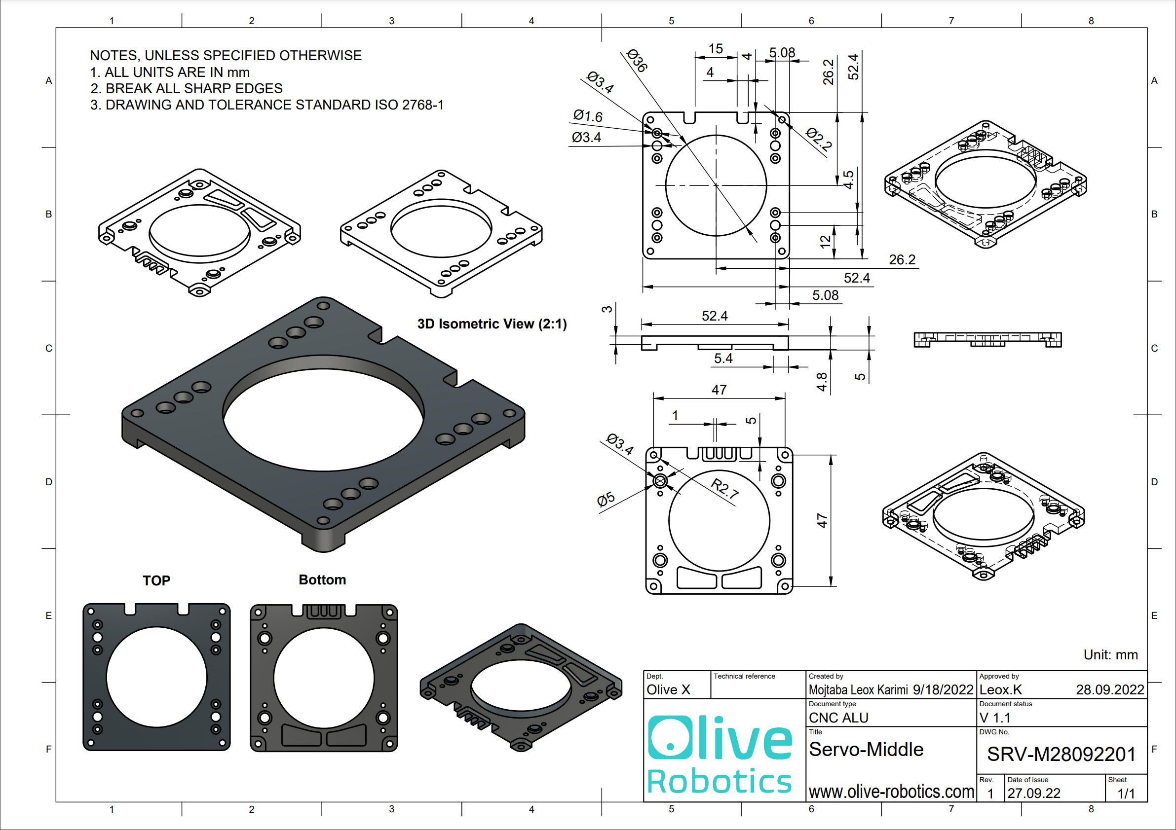
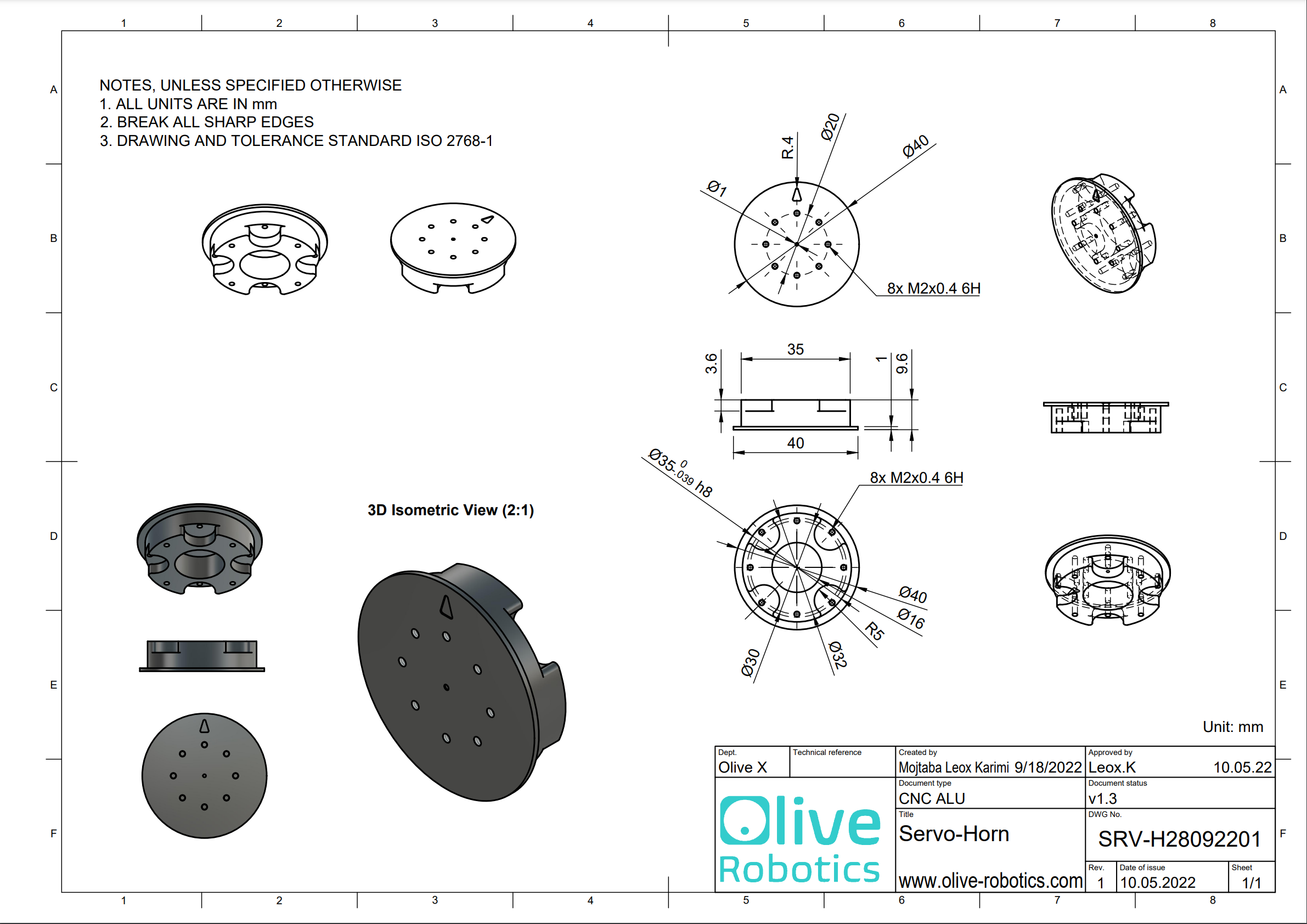
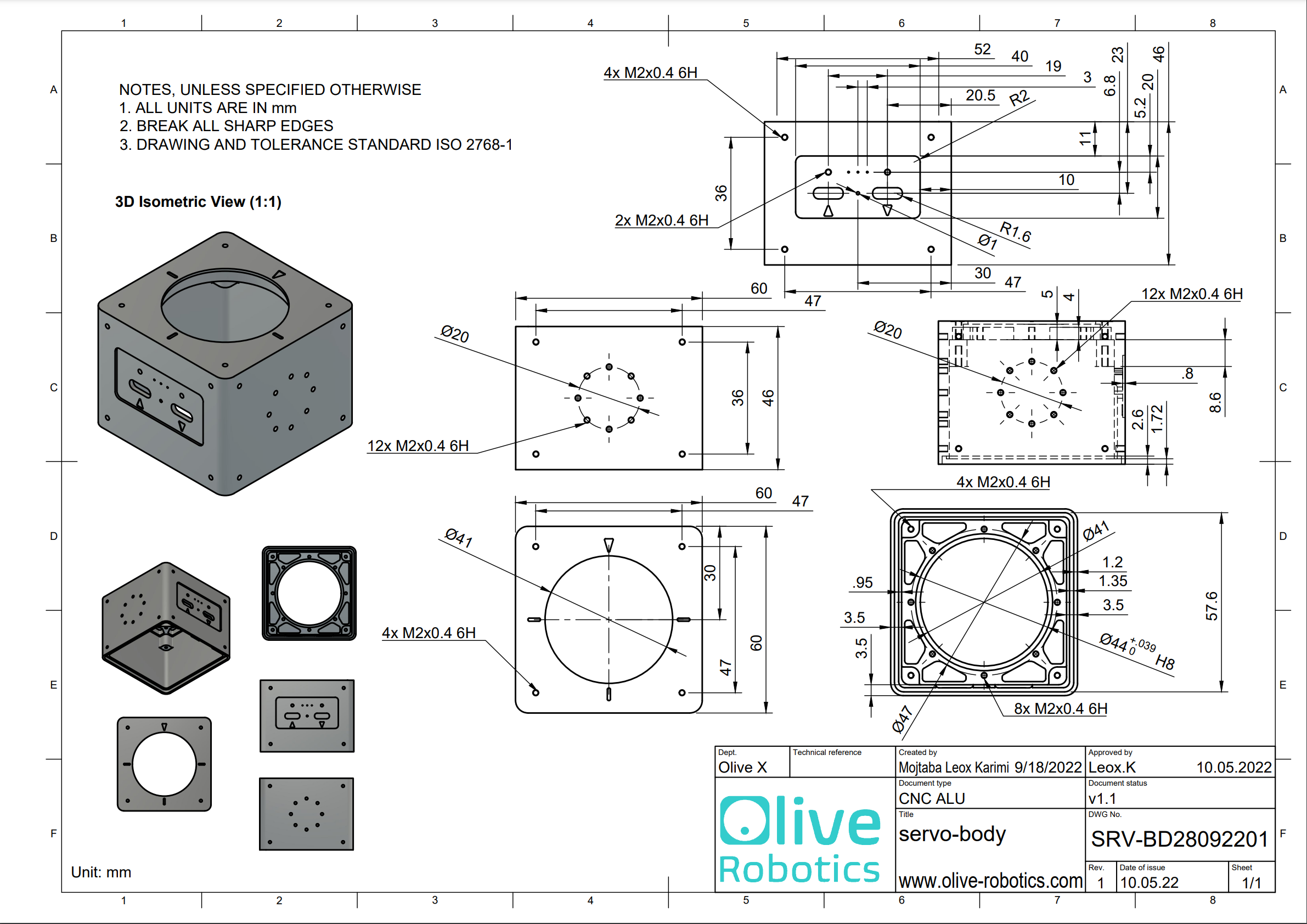
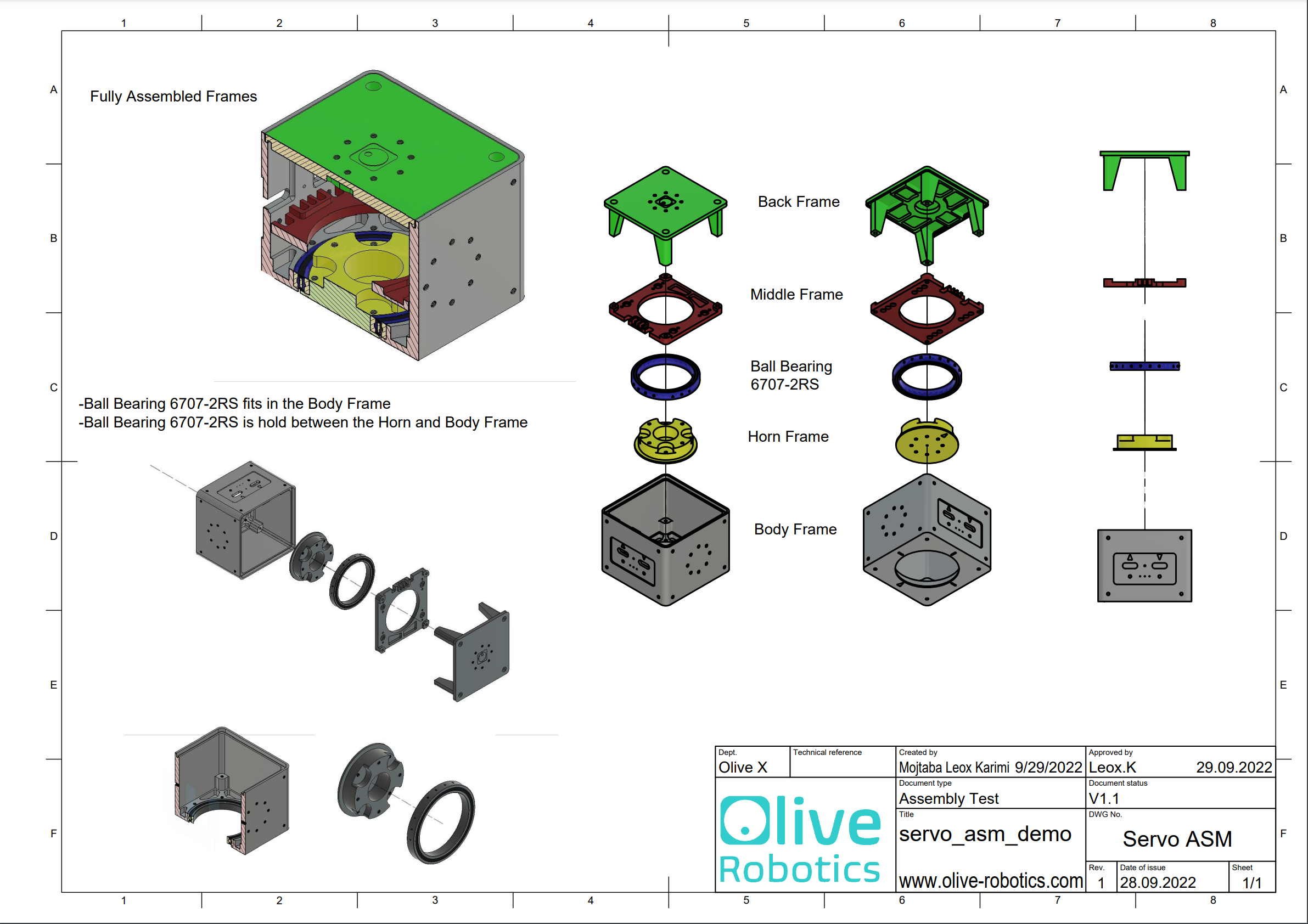
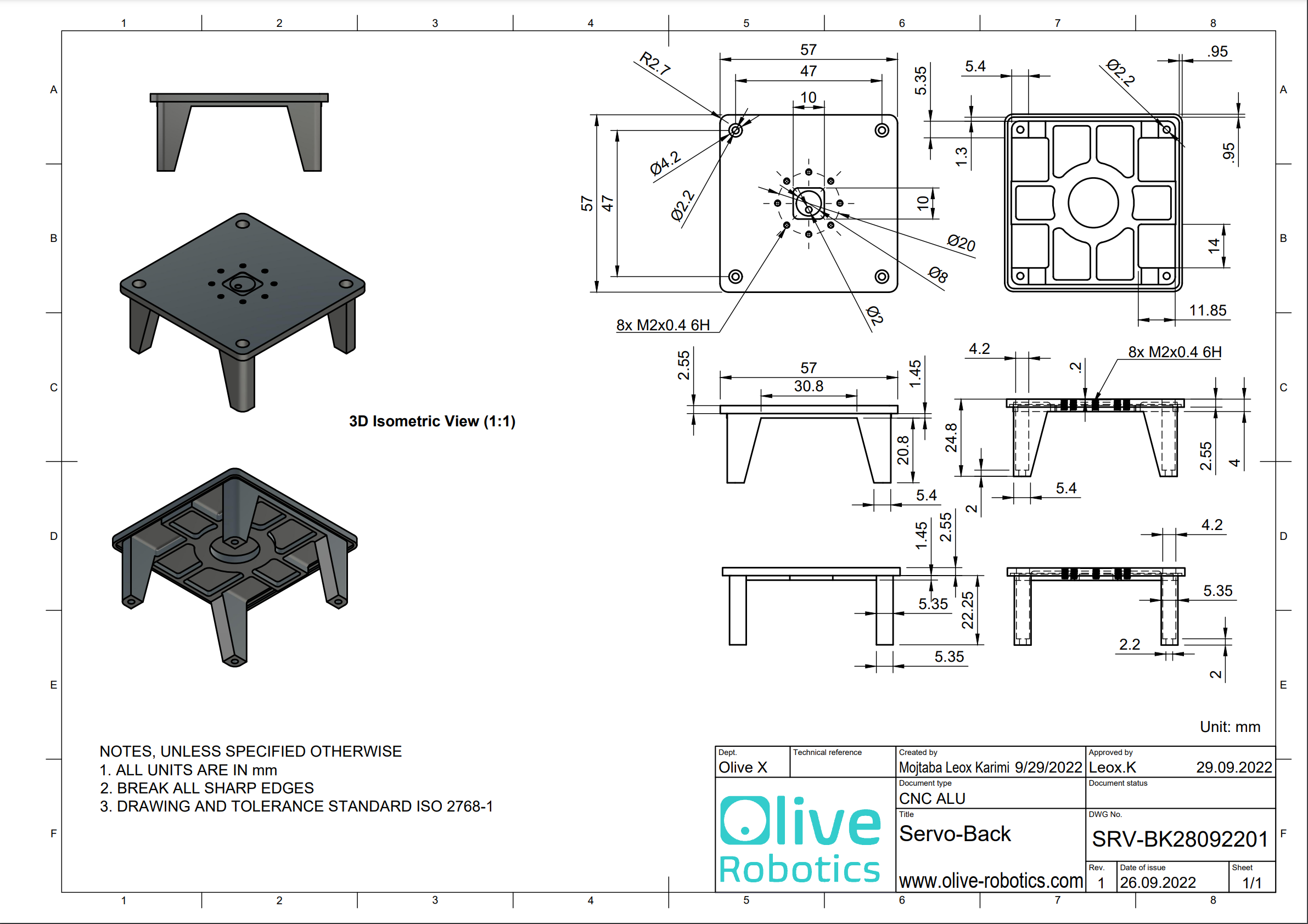
¶ Mechanical Details