Appearance
OLVX™-SRV-U01X64R
(software patch > 1215)
Overview
The olive® Servo the easiest way to get your own robotic system moving! This high-performance robotics component is designed for use in a wide range of applications. It is re-programmable and easy to integrate, making it simple for users to build their own custom robots and automated systems. The actuator has a plug and play design, making it quick and easy to install and set up, and it is compatible with multiple robotic operating systems, giving users flexibility in terms of the software tools they can use.

Key Features
ROS and ROS2 out of the box. No setup required.
High-torque motor: The olive® Servo module features a high-torque motor that provides the power and torque needed to move heavy loads or to perform high-precision tasks.
Easy integration: The olive® Servo is designed to be easy to integrate into a variety of different robotic systems. It just works through plug and play.
Daisy-chainable: Extend your system's funcionality by plugging additional hardware into the olive® Servo's input port: be it any other olive® hardware component or another USB-C peripheral.
Various control modes: olive® Servo offers five different modes of control: raw control (pwm), position control, velocity control, trajectory control and wheel mode control.
Software-defined: The olive® Servo is software-defined, allowing users to customize its communication layer, behaviour, and functionality through software rather than hardware.
Auto-voltage: the olive® Servo can run in different voltage modes: 5 / 9 / 12V. The specific voltage is automatically adjusted to the power intake to ensure maximum performance in all conditions.
Demo

olive® Servo Models
The olive series of servos includes four different models that are distinguished by their rotations per minute (RPM). Each servo comes with with an on-board 9D high-performance IMU. These are the available options:
| Name | Type | Sensors | Max Data Rate | RPM | Information |
|---|---|---|---|---|---|
| OLV-SRV01-S16 | Servo + IMU | Rotary Position Sensor & IMU Sensor (9D) | 40000Hz / 100 Hz | 16 | High Torque Servo Motor & IMU |
| OLV-SRV01-S32 | Servo + IMU | Rotary Position Sensor & IMU Sensor (9D) | 40000Hz / 100 Hz | 32 | Mid Torque Servo Motor & IMU |
| OLV-SRV01-S48 | Servo + IMU | Rotary Position Sensor & IMU Sensor (9D) | 40000Hz / 100 Hz | 48 | Mid RPM Servo Motor & IMU |
| OLV-SRV01-S64 | Servo + IMU | Rotary Position Sensor & IMU Sensor (9D) | 40000Hz / 100 Hz | 64 | High RPM Servo Motor & IMU |
Olive® Operational Modes
To change the servo mode you can open the debug gui and select the servo's mode:

1. PWM Control
Description: Pulse Width Modulation (PWM) control is a technique used to regulate the power supplied to electrical devices, such as actuators. It adjusts the duty cycle of the input signal, controlling the amount of power provided to the actuator.
- Input: Duty cycle (-1 to 1)
- Output: Power supplied to the actuator
- Subscriber topic: /olive/servo/name_space/pwm

2. Position Control
Description: Position control is used to maintain or adjust the position of an actuator. The controller computes the difference between the desired and actual positions and adjusts the actuator accordingly.
- Input: Desired position
- Output: Actual position of the actuator
- Subscriber topic: /olive/servo/name_space/goal/position
- PID: A PID controller is used to minimize the position error, adjusting the control signal to change the actuator's position.

3. Velocity Control
Description: Velocity control is used to maintain or adjust the velocity of an actuator. The controller computes the difference between the desired and actual velocities and adjusts the actuator accordingly.
- Input: Desired velocity
- Output: Actual velocity of the actuator
- Subscriber topic: /olive/servo/name_space/goal/velocity
- PID: A PID controller is used to minimize the velocity error, adjusting the control signal to change the actuator's velocity.

4. Trajectory Control
Description: This mode controls the position of the actuator, like position control does. But it does something extra: it uses a jitter buffer to give the PID controller a steady stream of data at regular intervals. This is especially useful when you're sending position targets over a network where timing isn't guaranteed. It's also great for situations where following the trajectory smoothly matters more than how fast it's executed.
- Input: Desired position
- Output: Actual position of the actuator
- Subscriber topic: /olive/servo/name_space/goal/position
- PID: A PID controller is used to minimize the position error, adjusting the control signal to change the actuator's position.

5. Wheel Control
Description: It operates similarly to velocity control but incorporates a watchdog mechanism designed to swiftly halt the motor if velocity commands fail to arrive within an assured interval. This feature is particularly valuable in wheel mode control scenarios, where preventing the robot from unintended movement due to high-level logic crashes or network issues is essential.
- Input: Desired velocity
- Output: Actual velocity of the actuator
- Subscriber topic: /olive/servo/name_space/goal/velocity
- PID: A PID controller is used to minimize the velocity error, adjusting the control signal to change the actuator's velocity.

Technical Specifications
| Part Number | OLV-SRV01-S* |
|---|---|
| Connection Interface | USB Type-C |
| Communication | USB Type C - Ethernet Over USB |
| Communication Protocol | ROS 1&2 (Virtual Ethernet / IPV4) |
| Rotations per Minute | 16 / 32 / 48 / 64 |
| Motor Control Pulse Duration | 1000kHz |
| Rotaray Position Resolution | 16384 |
| IMU Sample rate | 100 Hz |
| Gyroscope range | +/- 2000 deg/sec |
| Accelerometer range | +/- 16 g |
| Magnetometer range | +/- 4 gauss |
| Gyroscope accuracy | +/- 0.05 deg/sec |
| Accelerometer accuracy | +/- 0.1 g |
| Magnetometer accuracy | +/- 0.2 gauss |
| Performance Metrics | Covariance Matrix |
| Operating Voltage | 5.0V / 9.0V / 12.0V (auto adjusted) |
| Voltage Read Resolution | 65536 |
| Weight | 180 grams |
| Dimensions WxHxD | 60x60x46 mm |
| Native ROS Messages | sensor_msgs/JointState, sensor_msgs/Imu*, sensor_msgs/Temperature |
| Operating Temperature | 0 ~ 55 °C |
Quick Setup
Follow the Quick Start Guide for Olive Robotics robot modules to connect the device and start using it.
When the servo is correctly connected to your system, you can check that the expected ros topics are present. On your host PC run:
ros2 topic listros2 topic listThe following ROS topics showed be shown:
/olive/servo/id01/pwm
/olive/servo/id01/magnet/angle
/olive/servo/id01/magnet/moving_average
/olive/servo/id01/magnet/auto_gain
/olive/servo/id01/magnet/magnitude
/olive/servo/id01/magnet/diagnostic
/olive/servo/id01/joint
/olive/servo/id01/joint/voltage
/parameter_events
/rosout
/olive/servo/id01/pwm /olive/servo/id01/magnet/angle /olive/servo/id01/magnet/moving_average /olive/servo/id01/magnet/auto_gain /olive/servo/id01/magnet/magnitude /olive/servo/id01/magnet/diagnostic /olive/servo/id01/joint /olive/servo/id01/joint/voltage /parameter_events /rosout
INFO
The number id01 is your device's default namespace.
Control the servo and visualize the data using one of the available options.
Change the parameters like IP, ROS topic name, etc. using the embedded web interface.
Voltage Splitter for PD motors
If your motor is PD-enabled, it offers compatibility with both 12V batteries and external power sources. Activating the PD mode requires using the splitter and connecting the data and power cables as illustrated in the accompanying image:

Daisy Chain with Voltage Splitter

ROS Topics and Services
PWM Control Mode (Base topics)
| Topic Name | Message Type | Type | Description |
|---|---|---|---|
| .../pwm | std_msgs/Float32 | Subscriber | Control the raw pwm control value. -1.0 to 1.0 |
| .../magnet/angle | std_msgs/Float64 | Publisher | Current angular position of the servo. [radian] |
| .../magnet/moving_average | std_msgs/Float64 | Publisher | Moving average of .../magnet/angle [radian] |
| .../magnet/auto_gain | std_msgs/Byte | Publisher | The rotary sensor's auto gain register. |
| .../magnet/magnitude | std_msgs/Float64 | Publisher | The rotary sensor's magnitude register. |
| .../magnet/diagnostic | std_msgs/String | Publisher | The rotary sensor's diagnostic status. |
| .../joint | sensor_msgs/JointState | Publisher | The servo current joint state. |
| .../joint/voltage | std_msgs/Float64MultiArray | Publisher | The servo current joint state. |
Position Control Mode (Additional topics)
| Topic Name | Message Type | Type | Description |
|---|---|---|---|
| .../goal/position | std_msgs/Float32 | Subscriber | Desired position |
Velocity Control Mode (Additional topics)
| Topic Name | Message Type | Type | Description |
|---|---|---|---|
| .../goal/velocity | std_msgs/Float32 | Subscriber | Desired velocity |
Services
| Service Name | Type | Description |
|---|---|---|
| .../setZero | std_srvs/Trigger | Redefine the servo's current position to be zero. |
| .../setTorqueEnable | std_srvs/Trigger | Enables the servo torque. |
| .../setTorqueDisable | std_srvs/Trigger | Disables the servo torque. |
Advanced Settings
The device allows certain parameters to be changed at runtime. To get an overview of all changeable parameters use ros2 param list. To change a parameter use ros2 param set /dcm_actuator <parameter> <new_value>
Servo
PWM Control Mode (Base params)
| Parameter | Type | Range Min | Range Max | Default | Description |
|---|---|---|---|---|---|
| frequency | int | 0 | 1000 | 100 | Actuator status publish rate |
| lpf_velocity_gain | double | 0.0 | 1.0 | 0.9 | Low pass filter gain for velocity |
Position Control Mode (Additional params)
| Parameter | Type | Range Min | Range Max | Default | Description |
|---|---|---|---|---|---|
| Kd | double | 0.0 | 1000.0 | x | PID's derivative parameter |
| Ki | double | 0.0 | 1000.0 | x | PID's integral parameter |
| Kp | double | 0.0 | 1000.0 | x | PID's proportional parameter |
| control_frequency | double | 0.0 | 10000.0 | x | PID's control loop rate |
| error_threshold | double | 0.0 | 10.0 | x | PID's error threshold |
| limit_max | double | -pi | pi | pi/2 | Higher limit of joint workspace |
| limit_min | double | -pi | pi | -pi/2 | Lower limit of joint workspace |
| pwm_max | double | 0 | 1 | 1 | Maximum internal PWM power threshold |
Velocity Control Mode (Additional params)
| Parameter | Type | Range Min | Range Max | Default | Description |
|---|---|---|---|---|---|
| Kd | double | 0.0 | 1000.0 | x | PID's derivative parameter |
| Ki | double | 0.0 | 1000.0 | x | PID's integral parameter |
| Kp | double | 0.0 | 1000.0 | x | PID's proportional parameter |
| control_frequency | double | 0.0 | 10000.0 | x | PID's control loop rate |
| error_threshold | double | 0.0 | 10.0 | x | PID's error threshold |
| limit_max | double | 0 | 10 | 10 | Higher limit of joint velocity |
| limit_min | double | 0 | 10 | 0 | Lower limit of joint velocity |
| pwm_max | double | 0 | 1 | 1 | Maximum internal PWM power threshold |
System
| Parameter | Type | Range Min | Range Max | Default | Description |
|---|---|---|---|---|---|
| frequency | int | 0 | 10 | 10 | System status publish rate |
Parameter GUI
RIG Reconfigure
The GitHub repository "rig_reconfigure" by teamspatzenhirn is a GUI tool designed for editing ROS 2 parameters at runtime. This tool seems to be specifically aimed at managing and modifying the parameters within ROS 2, a popular robotics middleware framework, providing a graphical interface for ease of use. The repository is public and licensed under the MIT license, indicating open-source availability. The primary programming languages used in the project are C++ and CMake. For more details, you can visit the repository here.
- Install from apt
sudo apt install ros-humble-rig-reconfiguresudo apt install ros-humble-rig-reconfigure- Run the rig
ros2 run rig_reconfigure rig_reconfigureros2 run rig_reconfigure rig_reconfigure- It will show your ros2 parameters and you can edit them simply

Advanced setup
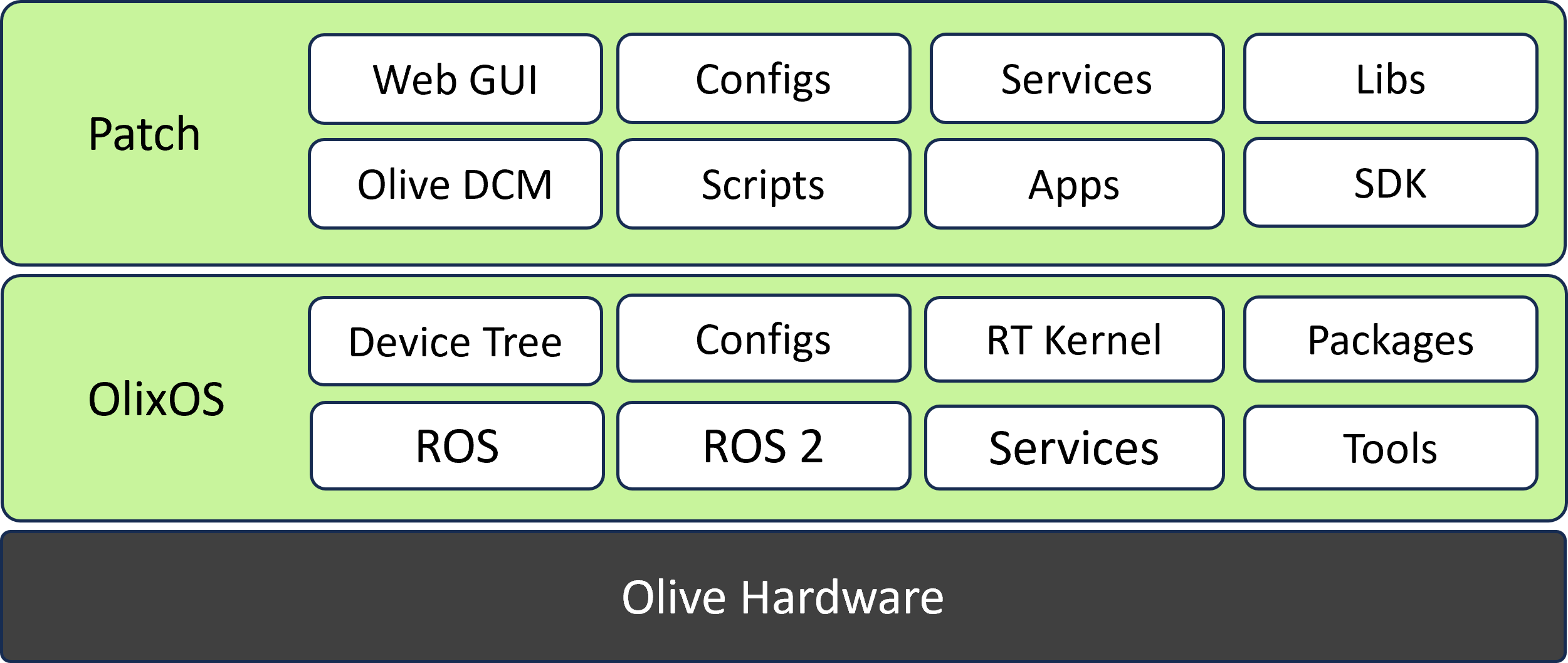
Olix-OS Real-Time Linux for Robotics
Olix-OS Linux is a version of the Linux operating system that is optimized for use on embedded systems, which are small, resource-constrained devices that are used in a wide range of applications such as industrial automation, consumer electronics, and the Internet of Things (IoT).
Olix-OS Linux is typically built using a small subset of the Linux kernel and a minimal set of user-space utilities and libraries. This allows it to run on devices with limited memory and processing power, and it also reduces the size of the operating system, making it more suitable for embedded systems.
Olix-OS Linux can be built using various build systems such as Yocto Project, Buildroot, and OpenEmbedded. These build systems provide pre-configured Linux distributions, which can be customized to suit the specific requirements of the embedded system. They also provide a set of tools for building and managing the Linux system, including the kernel, bootloader, and user-space utilities and libraries.
Olix-OS Linux is also highly configurable, which allows developers to fine-tune the operating system to meet the specific requirements of the embedded system. This includes configuring the kernel and user-space libraries, optimizing the system for performance, and selecting the appropriate drivers and software components.
One of the advantages of using Olix-OS Linux is that it is open-source, which means that developers have access to the source code of the operating system and can modify it to suit their needs. Additionally, embedded Linux has a large and active community of developers, which means that there is a wealth of documentation, support, and development tools available.
Overall, embedded Linux is a versatile and powerful operating system that is well-suited for use on embedded systems. It provides a small footprint and configurability, as well as a large library of pre-built software, making it a popular choice for developers and manufacturers alike.
Config Files
Olive config files are located at
/opt/olive/config/current/opt/olive/config/current
Here, for each component type, you will see a separate folder containing two types of YAML files. The first type is the config files, which are related to startup configurations, and the second type is the param files, which are related to real-time ROS parameter interactions.
Autorun your custom application
If you would like to enable autorun behavior for your custom application within the Olive components, you can add the executable command at the end of the app loader script. You can extend the script and add your logic to it.
/usr/bin/olive-app-loader.sh/usr/bin/olive-app-loader.shRestarting Services
After ssh in your component, you can start, stop or restart olive dcm services by using this commands.

for eio:
sudo systemctl restart olive-dcm-eio.servicesudo systemctl restart olive-dcm-eio.servicefor camera:
sudo systemctl restart olive-dcm-camera.servicesudo systemctl restart olive-dcm-camera.servicefor imu:
sudo systemctl restart olive-dcm-imu.servicesudo systemctl restart olive-dcm-imu.servicefor servo:
sudo systemctl restart olive-dcm-servo.servicesudo systemctl restart olive-dcm-servo.servicefor system:
sudo systemctl restart olive-dcm-system.servicesudo systemctl restart olive-dcm-system.servicefor manager:
sudo systemctl restart olive-sys-manager.servicesudo systemctl restart olive-sys-manager.servicefor app loader:
sudo systemctl restart olive-app-loader.servicesudo systemctl restart olive-app-loader.serviceFirmware Releases
| Format | Version | Link |
|---|---|---|
| Compressed IMG | 1.3.2 | download |
| Compressed IMG | 2.2.0 | download |
| Compressed IMG | 2.2.1 | download |
How can i see what is my current Software Patch?
In the Olive GUI dashboard in the device status group box you can see your current firmware version.
Flashing a New Image with Etcher Software
Introduction
Etcher is a free and open-source utility used to write image files such as .iso and .img files, as well as zipped folders onto storage media to create live SD cards and USB flash drives. It's widely used to flash OS images for Raspberry Pi, Arduino, and many other applications. Etcher is developed by balena, and it's available for Windows, macOS, and Linux.
Prerequisites
- An image file you want to flash, typically with a
.isoor.imgextension. (unzip the firmware file if it is compressed) - A USB drive or SD card with enough storage to accommodate the image file. (32 Gb or more)
- A computer with Etcher installed.
Step-by-Step Guide to Flashing an Image with Etcher
Step 1: Download and Install Etcher
- Navigate to Etcher's official download page.
- Choose the version of Etcher that corresponds to your operating system (Windows/macOS/Linux).
- Download the installer and run it. Follow the on-screen instructions to install Etcher on your system.
Step 2: Prepare Your USB Drive or SD Card
- Insert the USB drive or SD card into your computer.
- Ensure that there is no important data on the drive, as the flashing process will erase everything on it.
Step 3: Open Etcher and Select Image
- Open Etcher on your computer.
- Click on the “Flash from file” button.
- Navigate to the location where your image file is stored, select it, and click “Open” (or an equivalent, depending on your OS).
Step 4: Select Target
- Click on the “Select target” button.
- Choose your USB drive or SD card from the list. Be very careful to select the correct drive, as all data on the drive will be erased.
- Click “Connect” (or equivalent).
Step 5: Flash the Image
- Click on the “Flash!” button.
- Etcher will format the drive and write the image file to the USB drive or SD card. This process may take some time, depending on the size of the image file and the speed of the drive.
- Once the flashing process is complete, Etcher will validate the write to ensure it was successful.
Step 6: Eject Safely
- Once the flashing process is complete and validated, you can close Etcher.
- Eject the USB drive or SD card safely from your computer.
Step 7: Use the Flashed Drive
- You can now use the USB drive or SD card to boot a computer or power a device (such as a Raspberry Pi) depending on the image you flashed.
Troubleshooting Tips
- If Etcher fails to flash the image, try using a different USB port or card reader.
- Ensure that the image file is not corrupted. You might re-download the file or check its integrity if possible.
- Make sure your USB drive or SD card has enough space for the image file.
- If you experience persistent issues, consult the Etcher's GitHub repository or community forums for assistance.
Patch Update
Releases
| Format | Version | Min Firmware | Link | Note |
|---|---|---|---|---|
| SWU | 809 | 1.3.2 | download | - |
| SWU | 847 | 2.2.0 | download | - |
| SWU | 848 | 2.2.0 | download | - |
| SWU | 1004 | 2.2.0 | download | IMU v2.0 |
| SWU | 1025 | 2.2.0 | download | IMU v2.1 |
| SWU | 1026 | 2.2.0 | download | IMU v2.1 (No Magnetometer / Relative AHRS) |
| SWU | 1178 | 2.2.0 | download | IMU / CAM / Servo v2.3 |
| SWU | 1215 | 2.2.0 | download | IMU / CAM / Servo v2.4 |
| SWU | 1254 | 2.2.0 | download | IMU / CAM / Servo v2.5 |
| SWU | 1297 | 2.2.0 | download | IMU / CAM / Servo / EIO (Preview, not official) v2.5 |
1) If you are updating a patch for the first on a fresh OlixOS
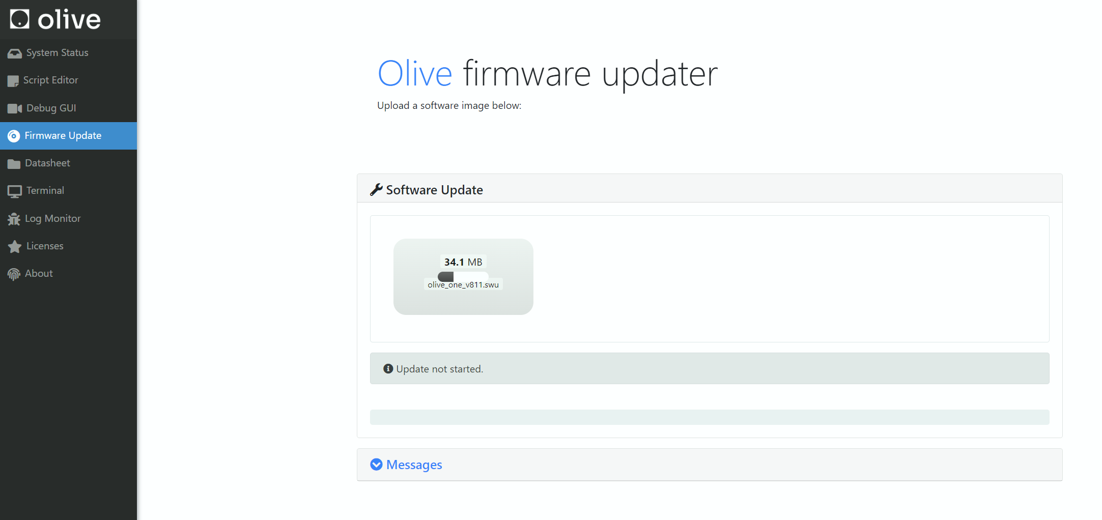
Fist open the update screen on your browser by going to <device_ip>:7070
then browse or drag and drop the (.swu) file olive_one_x.swu to the upload area. Then wait for a minute to software patch updater applies the software patch on your fresh OlixOS.
2) If you are updating a patch on a working OlixOS
Fist open the update screen by simply going to <device_ip> then select the Firmware Update from the left panel.
then browse or drag and drop the (.swu) file olive_one_x.swu to the upload area. Then wait for a minute to software patch updater applies the software patch on your current OlixOS.
How can i see what is my current Software Patch?
In the Olive GUI dashboard in the device status group box you can see your current software patch version
Environment Variables
In Olive components the permanent Environment Variables are located in:
/opt/olive/script/env.sh
In order to add your custom Environment variable you should declare it in this script, for example:
declare -x ROS_DOMAIN_ID="0"
SSH
How to log in
Logging in to a Linux real-time Olix-OS system using SSH (Secure Shell) is a common method for remotely accessing and managing the system. SSH is a secure protocol that allows you to remotely access the command line of a Linux system over a network connection.
To log in to a Linux real-time Olix-OS system using SSH, you will need a computer or device with an SSH client installed, and the IP address or hostname of the Olix-OS system.
The first step is to open the terminal or command prompt on your computer and type the command ssh olive@<IP_address> or ssh olive@<hostname> and press enter. This will initiate an SSH connection to the Olix-OS system.
Once the connection is established, you will be prompted for the password for the user account olive. You will need to enter the password one and press enter.
After providing the correct credentials, you will be logged in to the Olix-OS system and will have access to the command line interface. You can then issue commands to the Olix-OS system and perform various tasks such as configuring the system, managing files and processes, and monitoring system performance.
It's also important to note that SSH uses encryption to secure the communication between the client and the server, which means that your login credentials and data transmitted during the session will be protected against eavesdropping.
It's also important to mention that, depending on the real-time Olix-OS Linux distribution, the SSH daemon might not be enabled by default. It's recommended to check the system configuration and the usage of ssh service on the Olix-OS Linux before trying to connect to the system.
Network Configuration
1) Indipended device connection
You can set and update your device IP, netmask and gateway from the device dashboard GUI. More information Here:

2) Multi-Device Interoperability
Multi-Device / Servo Daisy Chain
When you connect multiple Olive components to your computer, they will appear as several Ethernet devices in your network adapter settings. In this configuration, it's necessary to either set up an internal network bridge or define static routes to ensure all devices are properly connected to your computer and can be pinged.
Daisy chain means you have an Olive servo in your setup and therefore you will need the Olive power spliter too. You can see the example network diagram below. Please note that the Olive camera in the daisy chain will work without automatically but for the IMU you will need to setup the connection manually.

Alternatively, you can daisy-chain multiple servos, adding a camera or IMU at the end of the chain. In daisy chain mode, network bridging is handled automatically, requiring no additional configuration.
In summary, using the daisy chain method results in only one Ethernet device being visible in your network device list, but you can still access and ping all devices in the chain. Conversely, connecting multiple components without daisy-chaining will show multiple devices in your network list. This arrangement typically requires manual setup, involving the creation of a bridge network or the definition of static routes to integrate all Ethernet interfaces connected to Olive components. Follow the relevant procedures to establish this setup.
Solution 1 (Statics Routing)
if this is your example network setup:

[imu 1: 10.42.0.7] => [pc interface: 10.42.0.1]
[imu 2: 10.42.0.8] => [pc interface: 10.42.0.2]
[imu 1: 10.42.0.7] => [pc interface: 10.42.0.1]
[imu 2: 10.42.0.8] => [pc interface: 10.42.0.2]then on your main pc try:
sudo ip route add 10.42.0.7 via 10.42.0.1
sudo ip route add 10.42.0.8 via 10.42.0.2
sudo ip route add 10.42.0.7 via 10.42.0.1
sudo ip route add 10.42.0.8 via 10.42.0.2Solution 2 (Network Bridge)
- Install the bridge-utils package:
sudo apt install bridge-utils
- First use the command "ifconfig" to see your current network interfaces:
ifconfigifconfigAs you can see in our example we have two Olive devices (enxa80000000001) and (enxa82c8d3c047b). We want to create a single bridge to internally connect this two interfaces and represents them with one ip address.

- Open the Network Manager connection editor GUI:
nm-connection-editor

click on (+) and select "Bridge" from the list

- In the Bridge connection Editor add your Olive network interfaces. Each time select "Add" then select "Ethernet"


from the device list select the Olive devices by the interface name or the MAC address. Here (enxa80000000001) and (enxa82c8d3c047b).

Once you done this step you will two interfaces in the list

- Change the Bridge ip to manual mode and define a static ip like:

It is better to select "10.42.0.x" or better "10.42.0.1" as shown in the picture.
- Remove extra (old) netwrok connections.


- Check the bridge connection:
sudo brctl show
This should display the bridge connection status between the Olive components.

- Test the connection with the "ping" command to ensure eveything is correct. In our case the first component has the ip address "10.42.0.7" and the second one has "10.42.0.8".

Internet Sharing
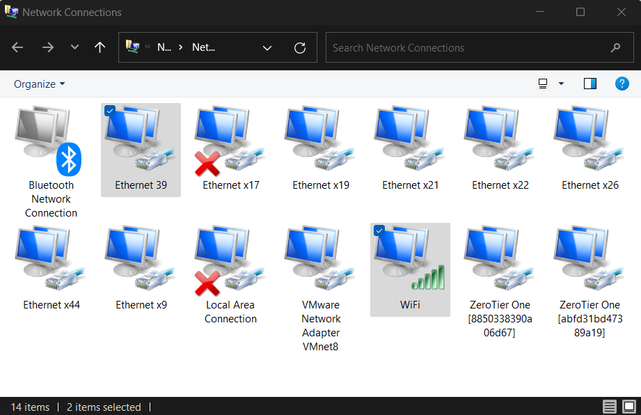
Windows
- First, open the Network Manager and identify your Olive network interface (in this case, "network 39"). Also, identify the interface through which you wish to share the internet (in this context, the WiFi).
- Next, access the settings of the WiFi network. Navigate to the appropriate tab and select the "Internet Sharing" feature. From the dropdown list, choose the Olive interface (in this instance, "network 39").

- Once again, open the network settings for the Olive interface. Proceed to the IPv4 configuration and modify the predefined IP to match the default gateway IP of the Olive interface. By default, the gateway value is set to 10.42.0.1.


- Now, SSH into the Olive component and attempt to ping 8.8.8.8 to verify your internet connection. If successful, you should observe a successful ping response as shown below:

- If you wish to change the default gateway on the device, follow these commands on the Olive component:
sudo ip route del default #delete the default route
sudo ip route add default via 10.42.0.1 #add the default route
sudo ip route del default #delete the default route
sudo ip route add default via 10.42.0.1 #add the default routeLinux Method 1 (Wi-Fi internet sharing)
- Install Necessary Packages: Before you begin, ensure you have the net-tools and dnsmasq packages installed. These tools will help manage and share the network.
sudo apt update
sudo apt install net-tools dnsmasq
sudo apt update
sudo apt install net-tools dnsmasq- Use the following command to list your network interfaces:
ifconfigifconfig- Use the commands bellow to share your wifi internet (here wlp3s0) with you olive interface (here enxa80000000001). Replace this two interface names according to your wifi and olive interface name.
sudo sysctl -w net.ipv4.ip_forward=1
sudo iptables -t nat -A POSTROUTING -o wlp3s0 -j MASQUERADE
sudo iptables -A FORWARD -i enxa80000000001 -o wlp3s0 -j ACCEPT
sudo apt-get install iptables-persistentsudo sysctl -w net.ipv4.ip_forward=1
sudo iptables -t nat -A POSTROUTING -o wlp3s0 -j MASQUERADE
sudo iptables -A FORWARD -i enxa80000000001 -o wlp3s0 -j ACCEPT
sudo apt-get install iptables-persistent- Verify Internet Sharing: SSH into the Olive component and try pinging an external server to check if the internet connection is shared:
sudo ping 8.8.8.8sudo ping 8.8.8.8Linux Method 2 (Lan internet sharing)
- Install Necessary Packages: Before you begin, ensure you have the net-tools and dnsmasq packages installed. These tools will help manage and share the network.
sudo apt update
sudo apt install net-tools dnsmasqsudo apt update
sudo apt install net-tools dnsmasq- Use the following command to list your network interfaces:
ifconfigifconfig- Configure Network Manager:
- Open the Network Manager GUI.
- Identify your primary internet connection.
- Also, identify the Olive network interface you wish to share the internet with.
- Set Up Internet Sharing:
- Go to the settings of your primary internet connection.
- Navigate to the "IPv4" tab.
- Choose the "Shared to other computers" option from the "Method" dropdown menu.
- Restart Network Manager: After making the changes, restart the Network Manager to apply them:
sudo service network-manager restartsudo service network-manager restart- Verify Internet Sharing: SSH into the Olive component and try pinging an external server to check if the internet connection is shared:
sudo ping 8.8.8.8sudo ping 8.8.8.8Time Synchronization
Network Time Protocol (PTP)
Due to limitations in the USB protocol, achieving PTP synchronization is not feasible with our current USB version of the products. However, we are planning to support PTP with our upcoming Ethernet version, expected to launch next year.
Network Time Protocol (NTP)
Setting Up NTP Synchronization on Olive Components
Adding NTP Server IP:
- Access the GUI: Log into your Olive component's GUI.
- Configure NTP Settings: Find the network or time settings and enter the IP of your NTP server.
- Save and Reboot: Apply changes and reboot the component.
- Verify Time: Open a terminal,ssh to Olive, type
date, and check the time sync. - Deep Verify:
ntpq -p

olive@robotics:~$ ntpq -p
     remote           refid      st t when poll reach   delay   offset  jitter
==============================================================================
 0.debian.pool.n .POOL.          16 p    -   64    0    0.000   +0.000   0.002
 1.debian.pool.n .POOL.          16 p    -   64    0    0.000   +0.000   0.002
 2.debian.pool.n .POOL.          16 p    -   64    0    0.000   +0.000   0.002
 3.debian.pool.n .POOL.          16 p    -   64    0    0.000   +0.000   0.002
*192.168.7.100   79.133.44.138    2 u  172  256  377    0.294   -5.920   1.859
olive@robotics:~$ ntpq -p
remote refid st t when poll reach delay offset jitter
==============================================================================
0.debian.pool.n .POOL. 16 p - 64 0 0.000 +0.000 0.002
1.debian.pool.n .POOL. 16 p - 64 0 0.000 +0.000 0.002
2.debian.pool.n .POOL. 16 p - 64 0 0.000 +0.000 0.002
3.debian.pool.n .POOL. 16 p - 64 0 0.000 +0.000 0.002
*192.168.7.100 79.133.44.138 2 u 172 256 377 0.294 -5.920 1.859Installing an NTP Server on Your Host Computer
For Linux:
- Install NTP: Run
sudo apt-get update && sudo apt-get install ntp. - Edit Config: Modify
/etc/ntp.confto add public NTP server entries. - Restart NTP: Execute
sudo systemctl restart ntp.
For Windows:
- Enable NTP Server: Go to
Internet Timesettings in the Control Panel, set up synchronization with a server from pool.ntp.org, and clickUpdate now.
Note: Ensure UDP port 123 is open in your firewall for NTP traffic.
That's it! Your Olive system should now be synchronizing its time with the predefined NTP server.
Reset Factory
To perform a factory reset on your Olive device, press and hold the reset button for more than 10 seconds. During this time, the LEDs will start blinking between 6 to 10 seconds as a warning. If you continue holding the button, the LEDs will turn solid, indicating the initiation of the factory reset process. This will restore the device to its default settings, create a reset trigger, roll back to a stable software update, and then reboot the device.
DANGER
Please note that the factory reset will take up to 2 minutes, and the device will reboot several times. During this period, please do not remove the connection cable.
For a safe shutdown without a factory reset, hold the button for 2 to 6 seconds.
Olive Component Reset Instructions Summary
| Duration | Action | LED Indicator | Expected Outcome |
|---|---|---|---|
| Less than 2 sec | No Action | On (Off on release) | No action taken |
| 2 to 6 sec | System Shutdown | On (Off on release) | System shuts down safely |
| 6 to 10 sec | Warning for Reset | Blinking | LED blinks as a warning before factory reset |
| More than 10 sec | Factory Reset Initiated | Solid On then Off | Factory reset starts: reset trigger created, rollback to stable update, and twice reboot |
Reset Factory Procedure Demonstrations
General Example (IMU-U01X09D)

General Example (IMU-U02X09D)

Data Distribution Service (DDS) Middlewares
Supported DDS implimentations
| Product name | License | RMW implementation | Status |
|---|---|---|---|
| eProsima Fast DDS | Apache 2 | rmw_fastrtps_cpp | Full support |
| Eclipse Cyclone DDS | Eclipse Public License v2.0 | rmw_cyclonedds_cpp | Full support |
| RTI Connext | commercial, research | rmw_connext_cpp | - |
| Zetascale Zenoh | commercial, research | rmw_zenoh | - |
1. Fast DDS (formerly Fast RTPS)
The default DDS implementation for most ROS2 distributions.
- Repository: https://github.com/eProsima/Fast-DDS
- RMW package:
rmw_fastrtps_cpp
Example Configuration for Fast DDS on Olive Device
This configuration is maintained automatically in the system, and you don't need to change it. However, it's useful to be familiar with it. If desired, you can extend this configuration to your host computer as well. This becomes handy when you wish to modify the buffer size or blacklist certain network interfaces that you don't want to use in ROS2.
The configuraiton is located in
/opt/olive/config/current/fastdds.xml/opt/olive/config/current/fastdds.xml<?xml version="1.0" encoding="UTF-8" ?>
<dds>
<profiles xmlns="http://www.eprosima.com/XMLSchemas/fastRTPS_Profiles">
<transport_descriptors>
<transport_descriptor>
<transport_id>udp_config</transport_id>
<type>UDPv4</type>
<interfaceWhiteList>
<address>192.168.7.1</address>
</interfaceWhiteList>
<sendBufferSize>4259840</sendBufferSize>
<receiveBufferSize>4259840</receiveBufferSize>
</transport_descriptor>
</transport_descriptors>
<participant profile_name="participant_xml_profile_qos_socketbuffers" is_default_profile="true">
<rtps>
<userTransports>
<transport_id>udp_config</transport_id>
</userTransports>
<!-- Buffer sizes, has big effect on performance.
* Values
* Maximum set on boot: 2147483647 ~ 20MB,
* 4259840 ~ 4MB.
* 2129920 ~ 2MB - performance similar to 4MB
* 1048576 ~ 1MB - worse performance
* For some reason, setting the largest value decreases performance.
* Make sure to match the transport_descriptor values
-->
<!-- See comments in jetson.xml -->
<sendSocketBufferSize>4259840</sendSocketBufferSize>
<listenSocketBufferSize>4259840</listenSocketBufferSize><!-- Maximum set on boot: 2147483647, moderate is 2129920 -->
<useBuiltinTransports>false</useBuiltinTransports>
</rtps>
</participant>
</profiles>
</dds><?xml version="1.0" encoding="UTF-8" ?>
<dds>
<profiles xmlns="http://www.eprosima.com/XMLSchemas/fastRTPS_Profiles">
<transport_descriptors>
<transport_descriptor>
<transport_id>udp_config</transport_id>
<type>UDPv4</type>
<interfaceWhiteList>
<address>192.168.7.1</address>
</interfaceWhiteList>
<sendBufferSize>4259840</sendBufferSize>
<receiveBufferSize>4259840</receiveBufferSize>
</transport_descriptor>
</transport_descriptors>
<participant profile_name="participant_xml_profile_qos_socketbuffers" is_default_profile="true">
<rtps>
<userTransports>
<transport_id>udp_config</transport_id>
</userTransports>
<!-- Buffer sizes, has big effect on performance.
* Values
* Maximum set on boot: 2147483647 ~ 20MB,
* 4259840 ~ 4MB.
* 2129920 ~ 2MB - performance similar to 4MB
* 1048576 ~ 1MB - worse performance
* For some reason, setting the largest value decreases performance.
* Make sure to match the transport_descriptor values
-->
<!-- See comments in jetson.xml -->
<sendSocketBufferSize>4259840</sendSocketBufferSize>
<listenSocketBufferSize>4259840</listenSocketBufferSize><!-- Maximum set on boot: 2147483647, moderate is 2129920 -->
<useBuiltinTransports>false</useBuiltinTransports>
</rtps>
</participant>
</profiles>
</dds>2. Cyclone DDS
A lightweight, high-performance DDS implementation by Eclipse Foundation.
- Repository: https://github.com/eclipse-cyclonedds/cyclonedds
- RMW package:
rmw_cyclonedds_cpp
These are the most common DDS implementations used in ROS2. To switch between them, follow the instructions from the previous answer to set the RMW_IMPLEMENTATION environment variable to the desired RMW package.
The following ROS2 DDS implementations are available and open-source for ROS2 which you can change it acording to your need:
How to change DDS middleware on the Olive device?
The default DDS implementation on Olive components are Fast DDS. However Cyclone DDS is also supported. You can change the middleware implementation using the GUI:


How to change ROS2 DDS implementation to Cyclone DDS for the host computer?
Follow these steps to change the ROS2 DDS implementation to Cyclone DDS:
1. Install Cyclone DDS
First, make sure that Cyclone DDS is installed on your system. You can install it using the following commands for different platforms:
- Ubuntu:
sudo apt update
sudo apt install ros-humble-rmw-cyclonedds-cpp
sudo apt update
sudo apt install ros-humble-rmw-cyclonedds-cpp- macOS, Windows, or building from source:
Please refer to the official Cyclone DDS installation instructions at https://github.com/eclipse-cyclonedds/cyclonedds/blob/master/INSTALL.md
2. Set Cyclone DDS as the default DDS implementation
You can change the default DDS implementation by setting the RMW_IMPLEMENTATION environment variable. You can do this either temporarily or permanently.
Temporarily (for the current terminal session):
Bash (Linux and macOS):
export RMW_IMPLEMENTATION=rmw_cyclonedds_cppexport RMW_IMPLEMENTATION=rmw_cyclonedds_cppPowerShell (Windows):
$env:RMW_IMPLEMENTATION="rmw_cyclonedds_cpp"$env:RMW_IMPLEMENTATION="rmw_cyclonedds_cpp"
After setting the variable, you can run your ROS2 nodes in the same terminal, and they will use Cyclone DDS.
- Permanently:
To make the change permanent, add the corresponding export or $env command to your shell configuration file. For Bash, this is typically .bashrc or .bash_profile (Linux) or .bash_profile (macOS). For PowerShell, this is typically the $PROFILE script.
How to Verify the change?
To ensure that your ROS2 nodes are using Cyclone DDS, you can run the following command:
ros2 doctor --reportros2 doctor --reportLook for the "middleware" section in the report. It should show "rmw_cyclonedds_cpp" as the active middleware.
That's it! Now your ROS2 system is using Cyclone DDS as the default DDS implementation.
Example Configuration for Cyclone DDS on the host computer
INFO
On your host computer you need to tell Cyclone which network interface you want to use in your system. This is especially important when you have multiple network interfaces. In this example host IP is 10.42.0.1. (or 192.168.7.100 for newer versinos)
Then you need to add a variable in your .bashrc to define the location of your cyclone dds config. You need to tell where your cyclonedds.xml is located.
export CYCLONEDDS_URI="/home/[username]/cyclonedds.xml"export CYCLONEDDS_URI="/home/[username]/cyclonedds.xml"then you need to stop and start the ros2 daemon.
ros2 daemon stop
ros2 daemon start
ros2 daemon stop
ros2 daemon startPut this configuration in your host computers cyclonedds.xml.
<?xml version="1.0" encoding="UTF-8" ?>
<CycloneDDS xmlns="https://cdds.io/config" xmlns:xsi="http://www.w3.org/2001/XMLSchema-instance" xsi:schemaLocation="https://cdds.io/config https://raw.githubusercontent.com/eclipse-cyclonedds/cyclonedds/master/etc/cyclonedds.xsd">
    <Domain Id="any">
        <General>
            <Interfaces>
                <NetworkInterface address="10.42.0.1" priority="default" multicast="default" />
            </Interfaces>
            <AllowMulticast>default</AllowMulticast>
            <MaxMessageSize>65500B</MaxMessageSize>
        </General>
        <Tracing>
            <Verbosity>finest</Verbosity>
            <OutputFile>cyclonedds.log</OutputFile>
        </Tracing>
    </Domain>
</CycloneDDS>
<?xml version="1.0" encoding="UTF-8" ?>
<CycloneDDS xmlns="https://cdds.io/config" xmlns:xsi="http://www.w3.org/2001/XMLSchema-instance" xsi:schemaLocation="https://cdds.io/config https://raw.githubusercontent.com/eclipse-cyclonedds/cyclonedds/master/etc/cyclonedds.xsd">
<Domain Id="any">
<General>
<Interfaces>
<NetworkInterface address="10.42.0.1" priority="default" multicast="default" />
</Interfaces>
<AllowMulticast>default</AllowMulticast>
<MaxMessageSize>65500B</MaxMessageSize>
</General>
<Tracing>
<Verbosity>finest</Verbosity>
<OutputFile>cyclonedds.log</OutputFile>
</Tracing>
</Domain>
</CycloneDDS>Downloads
| Type | Format | Version | Link |
|---|---|---|---|
| 3D Models | |||
| OBJ | 1.0 | Download | |
| DAE | 1.0 | Download |
Mechanical Details


