¶ 4 Simulation
This section introduces the robot simulation environment of ANT1.
The simulation environment allows users to test robot functions, verify algorithms, and perform development without using physical hardware.
Using the simulation environment, users can explore and evaluate robot capabilities before receiving the physical product. This enables early familiarization with robot behavior, navigation performance, and system interfaces.
Users can also build custom simulation scenarios based on their specific application requirements. This allows verification of whether the robot performance and environment interaction meet deployment expectations.
During the development phase, simulation can be used to test and validate software features before deploying them to the real robot. This helps reduce development risks, improves testing efficiency, and prevents potential hardware-related issues.
Once validated in simulation, features can then be deployed to the physical robot for real-world testing and operation.
¶ 4.1 ROS2 / Gazebo
The simulation platform provides physics-based simulation for testing robot control, sensor processing, and navigation functions.
It is built on ROS2 and Ignition Gazebo, leveraging their mature ecosystem and strong community support to deliver a reliable and realistic simulation workflow.
With Gazebo’s physics engine and the ROS2 integration, the simulation accurately models robot–environment interactions. The mecanum drive plugin enables smooth and responsive omnidirectional motion, closely reflecting real-world behavior. In addition, the IMU and odometry sensor plugins provide realistic measurements with configurable noise characteristics, offering high-fidelity reference data for algorithm development and validation.
Combined with the ROS2 Nav2 stack, the simulation environment supports SLAM mapping and autonomous navigation, allowing users to evaluate the full pipeline—from perception and localization to path planning and motion control—before deploying to physical hardware.
¶ 4.1.1 Installation
The robot simulation environment is built on Ubuntu 22.04 and Ignition Gazebo Fortress.
Info:
If you are using Ubuntu 24.04, it is recommended to run the simulation using a Docker container with Ubuntu 22.04.
Clone the repository into your ROS2 workspace and build the project using colcon.
add a repository url
cd ~/your_ws/src
git clone <repository_url>

cd ~/your_ws
colcon build

source install/setup.bash
Dependencies (Optional)
To launch simulation and navigation , install the following packages:
sudo apt update
sudo apt install -y \
  ros-humble-ros-gz-sim \
  ros-humble-robot-localization \
  ros-humble-ros-gz-bridge \
  ros-humble-nav2-bringup \
ros-humble-slam-toolboxMake sure to source the workspace every time you open a new terminal.
echo "source ~/your_ws/install/setup.bash" >> ~/.bashrc
source ~/.bashrc
¶ 4.1.2 Launch Simulation
Before launching the simulation environment, select the robot base type by setting the environment variable:
export OLIXBOTANT1_BASE=ANT1After selecting the robot base configuration, the simulation will use the ANT1 robot model.
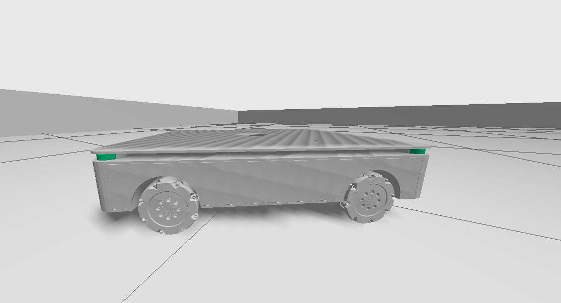
The ANT1 robot is equipped with mecanum wheels, enabling omnidirectional movement.
Four LiDAR sensors are mounted at the four corners of the robot to provide full surrounding environment perception.
The robot is also equipped with an IMU and odometry system for motion estimation and localization.
 |
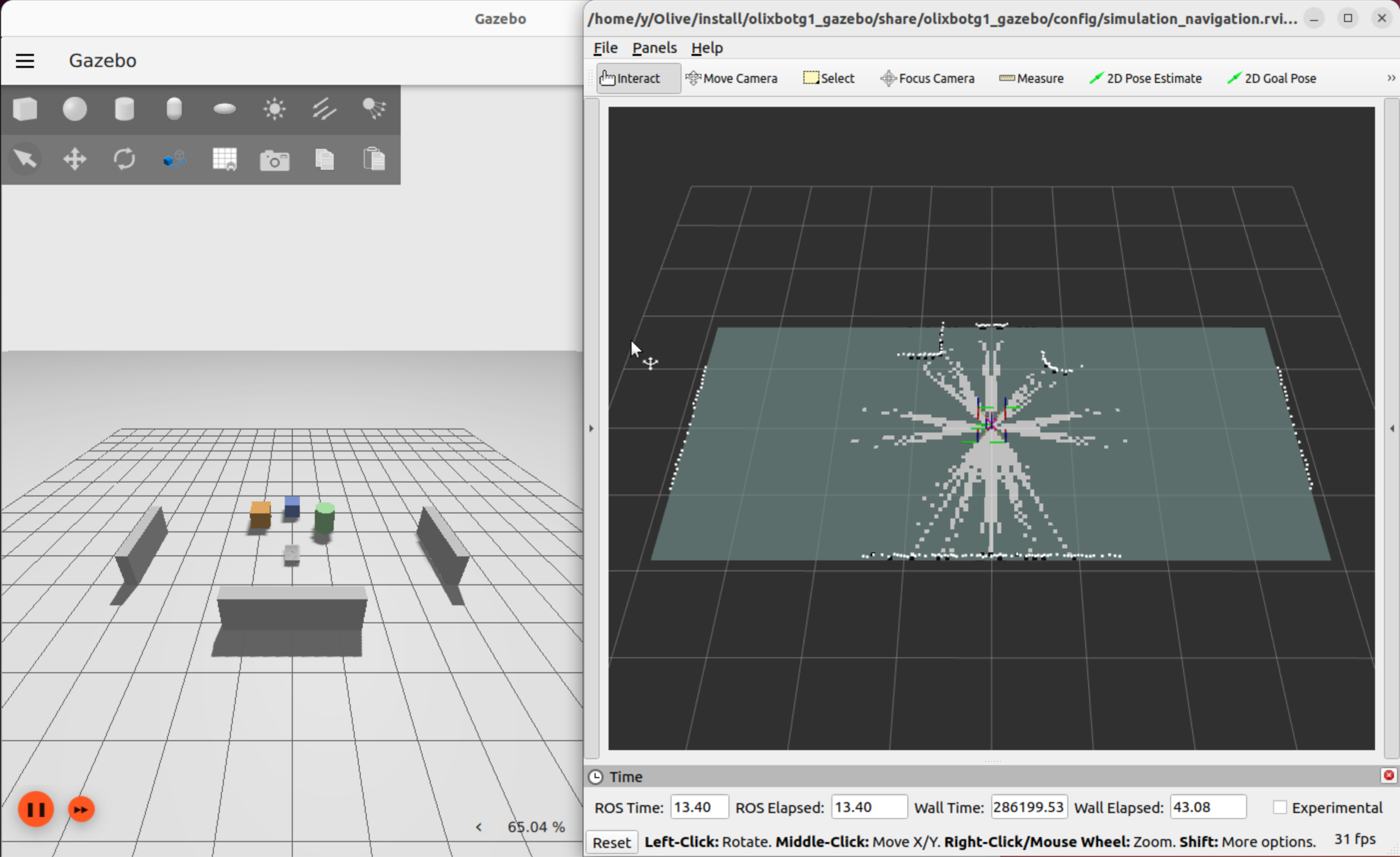
Then launch the Gazebo simulation environment together with the RViz2 visualization interface, and the SLAM process will start automatically.
ros2 launch olixbotant1_gazebo gazebo.launch_ant1.py
 |
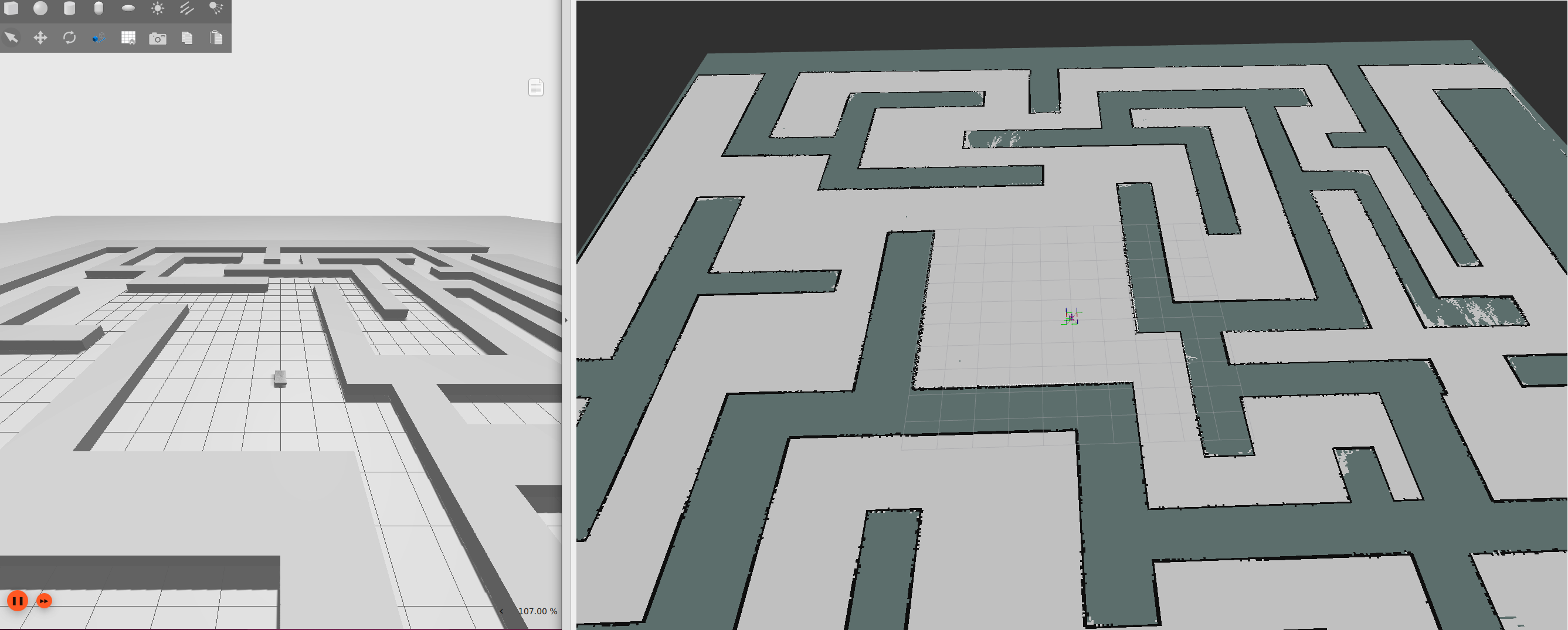
Alternatively, a pre-built maze map can be loaded. This map has been pre-scanned using SLAM.
ros2 launch olixbotant1_gazebo gazebo.launch_ant1.py \
    load_map:=maze.sdf \
map_name:=mazeAfter loading the map, the interface will appear as shown below:
 |
After the simulation is started, you can enable manual keyboard control:
ros2 run olixbotant1_gazebo keyboardControl.pyKeyboard Control Mapping:
Use the keyboard to control the robot movement:
W / S — Forward / Backward
A / D — Rotation
Q / E — Strafing (Left / Right)
I / N — Increase / Decrease linear speed
H / K — Increase / Decrease angular speed
Press Ctrl + C to exit manual control.
Warning:
Gazebo simulations can be CPU and GPU intensive. Running multiple large worlds or high-fidelity sensor plugins may cause:
- Low FPS (choppy simulation)
- High CPU temperature
- Simulation lag or time drift
Consider closing other heavy applications during simulation.
¶ 4.1.3 Simulation Interaction
After launching the simulation, the robot’s autonomous navigation function is available.
The robot can automatically plan and move to a specified target location.
To set a navigation goal, use RViz2:
- In the RViz2 toolbar (top-right), select the Set Goal / 2D Nav Goal tool, then click on the map to choose a target position and drag to set the desired orientation.
After the goal is configured, Nav2 automatically performs path planning and visualizes the computed path on the interface. The robot subsequently navigates along the planned trajectory.
¶ 4.1.4 Robot Architecture
In the SDF file, the robot model is configured with a mecanum drive system, IMU, wheel odometry, and multiple LiDAR sensors to simulate real-world hardware behavior.
The mecanum drive plugin simulates the directional (anisotropic) friction characteristics of mecanum wheels. This allows the simulation to reproduce realistic traction behavior, including smooth lateral movement and combined translation–rotation motion. Wheel odometry is generated from the simulated wheel motion and provides continuous estimation of robot displacement and velocity
The IMU sensor provides orientation, angular velocity, and linear acceleration measurements. These measurements help improve short-term motion estimation and stabilize pose estimation during rapid movement or wheel slip conditions.
All sensor and motion data are published to the ROS2 ecosystem using standard ROS2 topics. These data streams are used by higher-level modules such as localization, mapping, navigation, and control.
To improve localization accuracy, IMU data is fused with wheel odometry using an Extended Kalman Filter (EKF). The EKF combines multiple sensor inputs to reduce noise and drift, producing a more stable and accurate estimate of the robot pose, including position, orientation, and velocity.
This fused state estimation is used as the primary input for downstream modules such as SLAM mapping, navigation planning, and motion control.
¶ 4.1.4.1 ROS2 Topics Overview
The robot publishes and subscribes to multiple ROS2 topics to support sensor data streaming, state estimation, localization, and motion control.
These topics provide the primary communication interface between hardware drivers, perception modules, navigation stacks, and control systems.
¶ Raw Sensor Data
The robot is equipped with four LiDAR sensors and one IMU:
- /scan_front_left — Front-left LiDAR raw scan data
- /scan_front_right — Front-right LiDAR raw scan data
- /scan_rear_left — Rear-left LiDAR raw scan data
- /scan_rear_right — Rear-right LiDAR raw scan data
- /imu/data — IMU orientation and acceleration data
¶ Merged Sensor Data
- /scan — Combined LiDAR scan generated from all four LiDAR sensors
This merged scan is typically used by SLAM, mapping, and navigation modules.
¶ Robot State and Transforms
- /odom — Wheel odometry estimation
- /tf — Transform tree describing coordinate frame relationships
¶ Motion Control
- /cmd_vel — Velocity command input for robot movement
This topic accepts linear and angular velocity commands for robot motion control.
¶ 4.1.4.2 tf tree
The sensor and state estimation modules together generate and maintain the coordinate frame relationships represented in the TF tree below.
These transforms describe the spatial relationships between the map frame, odometry frame, robot base frame, and sensor frames in real time.
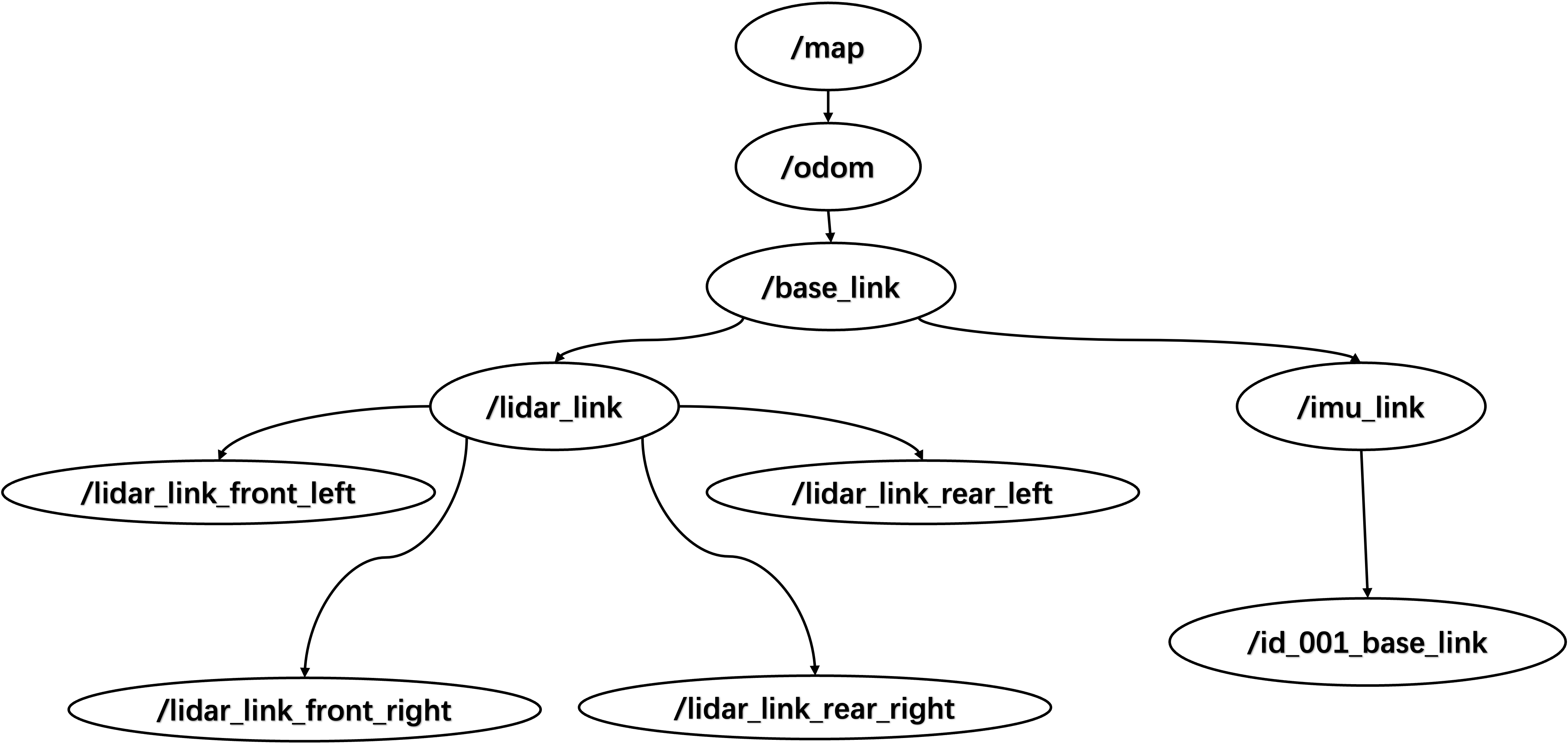 |
| Tf Tree Of Simulation Enviourment |
For the sensor frame configuration, most sensor frames are statically defined relative to the robot base frame:
- The four LiDAR sensors are statically transformed to their respective lidar_link frames, which are then transformed to the base_link frame.
- The IMU frame is directly attached to the base_link frame using a static transform.
For dynamic frames:
- The odom frame is dynamically updated based on the mecanum drive odometry.
- The map frame is generated by the SLAM system, which continuously updates the robot pose relative to the map using odometry and sensor observations.
¶ 4.1.5 Creating Your Own Environment Map
If you want to test the robot in a different environment, you can load or create a custom simulation world instead of using the default example scene.
Users can modify or create new testing world files to simulate different layouts, obstacles, or workspace conditions. This allows testing robot behavior in scenarios that better match real deployment environments.
Users can create their own simulation environments by adding a custom SDF world file under:
navigation/olixbotant1_gazebo/worlds/A new scene can be created by editing or copying an existing world file, such as:
mecanum_world.sdfOnce the custom world file is created, rebuild the workspace and source the environment before launching the simulation:
ros2 launch olixbotant1_gazebo gazebo.launch_ant1.py load_map:=your_world.sdf
Info:
Custom world files must be compatible with Ignition Gazebo Fortress. Unsupported model formats (e.g., old SDF versions) may cause simulation crashes or unexpected behavior.If you encounter errors when loading your custom world, check the console output and verify the SDF file version.
Info:
The load_map argument specifies the world file to load. If omitted, the default world will be used.Ensure your world file is available in the worlds/ directory and the filename matches exactly.
¶ 4.1.6 Troubleshooting
- If RViz2 reports missing frame errors, set the fixed frame to map.
- Ignition Gazebo has stronger native support for SDF (Simulation Description Format), and plugins configured through SDF typically run more reliably. When creating custom simulation environments or worlds, users are recommended to use SDF instead of other formats when possible.
¶ 4.2 IssacSim
Isaac Sim offers advanced physics simulation and high-fidelity material rendering, which allows realistic visualization of robot-environment interactions. It also enables integration with reinforcement learning (RL) pipelines for simulation-based training and testing. Leveraging these capabilities, an Isaac Sim-based simulation environment for the product is currently under active development.