¶ 2 Getting Started
This section provides a step-by-step introduction to using the robot for the first time.
It covers the essential procedures required to safely start operating the robot, including powering on the system, checking hardware status, establishing network or controller connections, and verifying that the robot is ready for operation.
You will also learn how to perform basic operations such as manual control, monitoring robot status indicators, and confirming that key subsystems (sensors, communication, and motion control) are functioning correctly.
This section is intended to help users quickly transition from unpacking the robot to performing their first successful operation.
Info:
It is strongly recommended to review the Safety Guidelines section before operating the robot for the first time. Please refer to the Safety Guidelines for important safety information and operating precautions.
¶ 2.1 Starting up the Robot
¶ 2.1.1 Power On
Press the power button to start the robot.
 |
| System Initialisation |
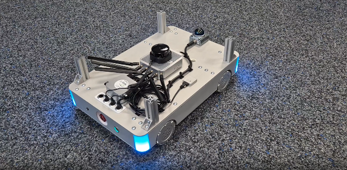
During startup, the status LED will blink blue, indicating that the system is booting. Booting may take some seconds.
 |
| Startup Process Finished |
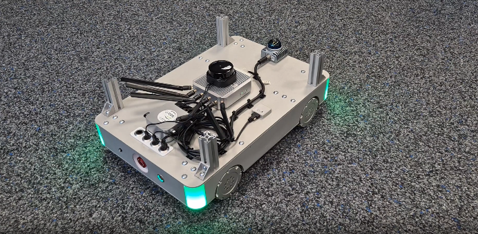
Once the startup process is complete, the LED will turn green, indicating that the robot is ready for operation.
At this point, the robot can be controlled and is ready to execute commands.
¶ 2.1.2 Power off
Press the power button to shut the robot down.
¶ 2.1.3 Charge
Insert the supplied charging cable into the robot charging port to start charging.
While charging, the robot must remain stationary and cannot be moved.
¶ 2.1.4 Emergency Button
Press the emergency stop button to immediately stop all robot motion.
 |
| Emergency Mode |
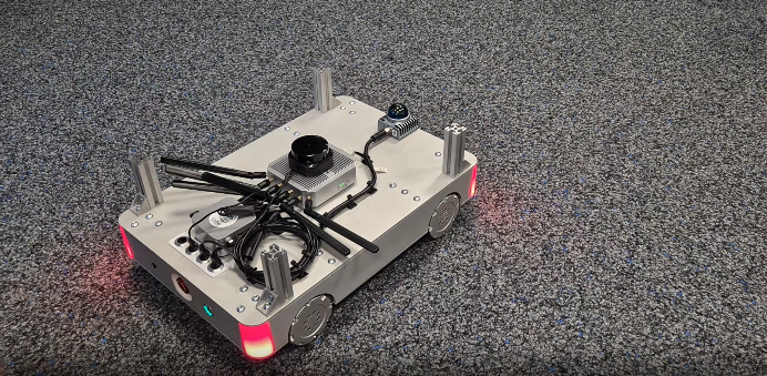
When the emergency stop is activated, the status LED changes from green to red, indicating that the robot is in emergency stop mode.
While in emergency stop mode:
- Robot motion is disabled
- Motor power is disconnected
- The robot cannot receive control commands
To resume operation, rotate the emergency stop button to release it.
After release, the LED returns to green, indicating normal operating state.
¶ 2.2 Manual Control
Warning:
Make sure the robot is disconnected from the charger before operating.
Turn on the joystick controller to start manual control.
The controller will automatically connect to the robot.
Once the connection is successful, the controller status LED will turn light green. Press and hold the L1 button to enter manual control mode.
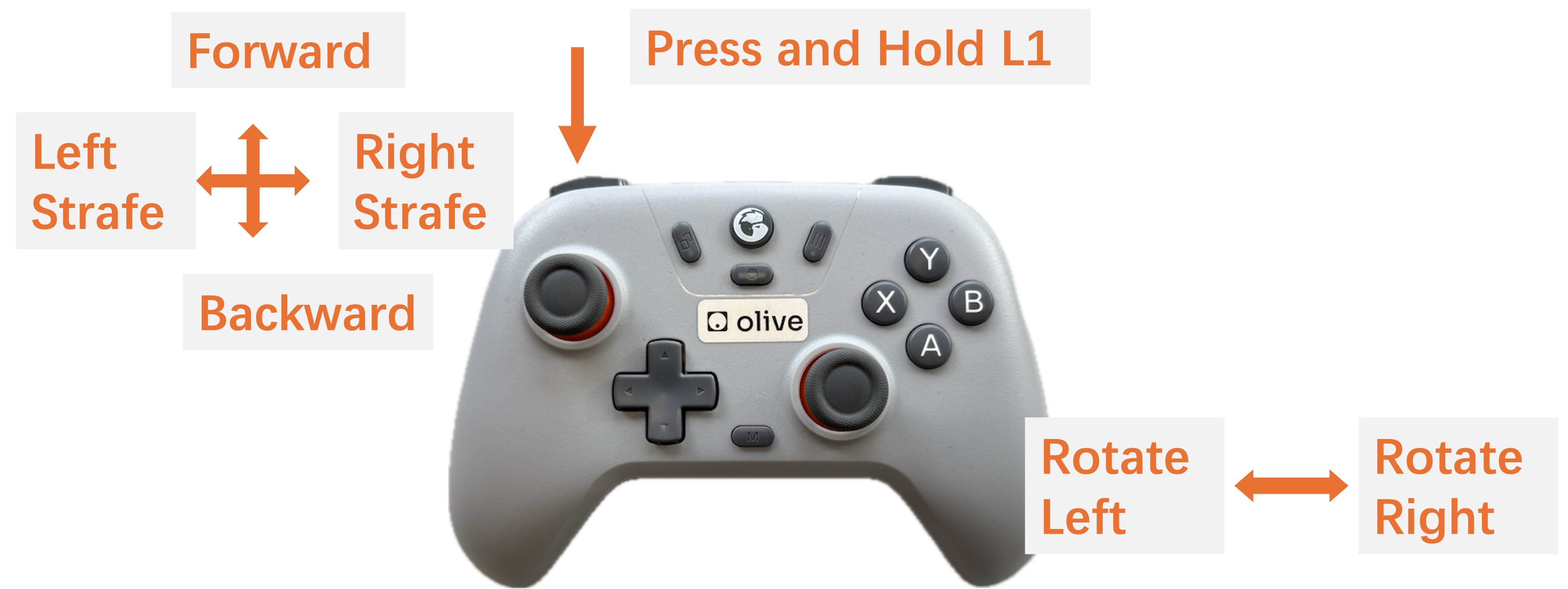 |
| Robot Motion Control Mapping |
When manual control mode is active, the robot status LED will turn blue.
During manual control:
- The left joystick (left/right) controls forward/backward movement and lateral movement (side-to-side strafing).
- The right joystick controls robot rotation.
¶ 2.3 Configuration Before First Connection
Before operating the robot, you need to set up the connection. This section guides you through establishing and checking the connection to make sure the robot can be controlled correctly.
¶ 2.3.1 ROS 2 & Cyclone DDS
The ANT1 runs on Cyclone DDS by default. To receive data on your host system, switch your host middleware to Cyclone DDS as well.
¶ Install and Setup Cyclone DDS
Install Cyclone DDS via following command
sudo apt install ros-humble-rmw-cyclonedds-cppTell ROS 2 to change to cyclone via following command
export RMW_IMPLEMENTATION=rmw_cyclonedds_cpp
- To make it permanent add the line above into the .bashrc
If you want a specific configuration, you can add a custom config using the following command:
CYCLONEDDS_URI=path/to/custom/cyclone/config.xml
¶ 2.3.2 Adapting to Network Changes
ROS 2 can be very sensitive to network changes. In particular, when the currently preferred network interface (for example Ethernet/LAN) suddenly becomes unavailable and the system falls back to another interface (such as Wi-Fi), ROS 2’s discovery mechanism may stop working correctly. This behaviour can also occur when connecting to the ANT1 Router. In these cases, ROS 2 topics can appear “stuck” and no messages are shown anymore, even though the nodes are still running.
If you encounter issues such as missing or undiscoverable topics, you can try restarting the ROS 2 daemon using ros2 daemon stop. The following section provides a detailed explanation of the ros2 daemon stop command and how it helps restore normal topic discovery.
How to change the network then?
- Stop the ros2 daemon
ros2 daemon stop
- Change your network (e.g. unplug LAN, connect to the ANT1 Router, adjust/remove the priority network, etc.).
- Start the ros2 daemon
ros2 daemon start
¶ 2.3.2.1 Prioritizing the ANT1 Network for ROS 2 Communication
If you are running two networks in parallel on your host system (for example, a regular LAN connection and the ANT1 network over Wi-Fi), your operating system may prioritize the non-ROS network by default. This can cause ROS 2 traffic to be sent over the “wrong” interface, leading to missing topics or unstable communication with the ANT1 system.
To ensure that ROS 2 (Cyclone DDS) uses the ANT1 network interface, you can provide a custom Cyclone DDS configuration that explicitly selects the desired interface:
<?xml version="1.0" encoding="UTF-8" ?>
<CycloneDDS xmlns="https://cdds.io/config"
            xmlns:xsi="http://www.w3.org/2001/XMLSchema-instance"
            xsi:schemaLocation="https://cdds.io/config https://raw.githubusercontent.com/eclipse-cyclonedds/cyclonedds/master/etc/cyclonedds.xsd">
    <Domain Id="any">
        <General>
            <Interfaces>
                <NetworkInterface name="ANT1 Network Interface Name"/>
            </Interfaces>
            <AllowMulticast>true</AllowMulticast>
        </General>
    </Domain>
</CycloneDDS>
Replace "ANT1 Network Interface Name" with the actual name of the network interface used by the ANT1 router (as shown by ip a, ifconfig, or your OS’s network settings).
Then restart the ROS 2 daemon with this configuration:
ros2 daemon stop
export CYCLONEDDS_URI=/path/to/custom/cyclone_dds/config.xml
ros2 daemon start
With this setup, Cyclone DDS will prefer the specified ANT1 interface for ROS 2 communication, even if another network (such as LAN) is otherwise prioritized by the host system.
Then to make it permanent add the line
export CYCLONEDDS_URI=/path/to/custom/cyclone_dds/config.xmlinto your .bashrc.
¶ 2.4 First Connection
ANT1 can be connected via WiFi or Ethernet. Once the network connection is established and your computer is on the same network, you can access the robot using SSH.
¶ 2.4.1 Environment Setup
To run the Mapping, Navigation and the Waypoint Server, please download the ANT1 repository in your ros2 workspace first. (see how to create a ros2 workspace)
¶ 2.4.2 SSH Connection
The computer of the robot can be accessed over ssh.
- Power on the OlixBot™ ANT1 and wait until the system has fully booted.
- Connect to the WIFI router of the robot: SSID: olixLink-C1 PW: olixLink
- ssh with following command:
ssh firefly@192.168.7.200or
ssh firefly@192.168.7.98PW: one
Info:
To establish a connection with the robot, you will use a terminal application (Command Prompt on Windows, Terminal on Linux or macOS).
¶ 2.4.3 Change password
For security reasons, it is strongly recommended to change the default SSH password before deploying the robot in a production or networked environment.
You can change the password using the standard Linux
passwd command after logging in via SSH.
- You will then be prompted to enter the current password and press Enter.
- Next, enter a new password containing at least 8 characters. You will be required to enter the new password twice for confirmation, pressing Enter after each entry.
- For security reasons, the password will not be displayed while typing. If the change is successful, a confirmation message will be shown.
To cancel the password change, press CTRL + U, then CTRL + D. The system will display passwd: password unchanged.
Info:
Refer to your system administrator if required.
Warning:
Please ensure that the new password is stored securely. If the password is lost, you will need to contact Olive Robotics for system reset.
¶ 2.5 Creating and saving a new map
This section explains how to create a new map using the robot’s SLAM functionality.
Mapping allows the robot to build a representation of its environment, which is required for autonomous navigation. By scanning the surroundings with its LiDAR sensors while moving through the area, the robot generates a 2D occupancy map that can later be used for localization and path planning.
This procedure is typically performed when deploying the robot in a new environment or when significant changes have been made to an existing workspace.
Once the mapping process is complete, the generated map can be saved and reused for future navigation tasks.
Warning:
During LiDAR-based SLAM operation, the robot uses 2D LiDAR sensors to detect and map the environment.
Because the LiDAR performs scanning in a single horizontal plane, objects located below the LiDAR mounting height are outside of the sensing range. Operators should verify that the operating area is free of low-height obstacles or hazards that cannot be detected by the LiDAR sensors.
¶ 2.5.1 Visualization
All map visualization and monitoring tasks during the following steps are performed using RViz2, which is included in the ROS2 Desktop installation.
To simplify the workflow, a preconfigured RViz2 layout is provided. This preset interface includes the necessary visualization tools and display settings for mapping and navigation, allowing users to focus on the operation without additional manual configuration.
For visualizing the mapping process, the file ant1_slam.rviz is available in the ANT1 repository.
Run the following command on your host system to launch RViz2 with the predefined configuration:
ros2 run rviz2 rviz2 -d <PATH\TO\WORKSPACE>/rivz/ant1_slam.rvizThe provided configuration ensures that map data, robot pose, sensor information, and navigation elements are displayed consistently throughout the process.
¶ 2.5.2 Start Mapping
then to start creating a new map:
- Connect WiFi of ANT1
- SSH into the robot
- Run the slam.sh script under the scripts directory. This stars the mapping.
- Now you should see a map, when driving with the robot the map should be updated
Info:
If the environment has changed significantly after a map was created, localization accuracy may degrade, leading to repeated navigation failures. To ensure reliable operation, create a new map that reflects the current state of the environment.
Warning:
The robot relies on LiDAR sensors for environment perception and obstacle detection.
Due to the physical characteristics of LiDAR sensing, certain materials may be difficult to detect, including transparent surfaces (e.g., glass) and highly absorptive or low-reflectivity surfaces (e.g., matte black objects). These surfaces may result in weak or missing LiDAR returns, which can reduce detection reliability.
Warning:
The mapping process may become unstable in long, narrow corridors due to limited environmental features. In such cases, localization drift or scan-matching errors may occur, potentially requiring a restart of the mapping process.
¶ 2.5.3 Saving the Map
After the mapping process is completed, the generated map can be saved for later use.
- SSH into the robot
- Run following command to save the map:
ros2 run nav2_map_server map_saver_cli -f map
This will save a map.pgm and a map.yaml file. The -f flag specifies the output file name. You can also provide a custom path, for example:/home/maps/first_map - Once saved, the map can be loaded and used for localization and autonomous navigation.
Info:
Before saving the map, confirm in RViz2 that the scan data properly matches the real environment. Only save the map once alignment is accurate and stable.
¶ 2.6 Navigation
Once a map has been successfully created and saved, the robot can be used for autonomous navigation.
Using the stored map, the robot performs localization to determine its position within the environment and plans collision-free paths to target locations. This enables fully autonomous movement based on the previously generated map data.
In the following steps, you will learn how to load the saved map and send navigation goals to the robot.
¶ 2.6.1 Start Navigation
- SSH into the robot
- Run the navigation script located in the scripts directory:
navigation.sh --map map.yaml--map: Path to the previous created map (is has to be the *.yaml file) - Launch RViz2 to monitor the navigation system and verify that the map is correctly loaded. A preconfigured RViz2 layout file named ant1_navigation.rviz is provided in the ANT1 repository. Run the following command on your host system:
ros2 run rviz2 rviz2 -d <PATH\TO\WORKSPACE>/rivz/ant1_navigation.rviz
Once RViz2 is running:
- Confirm that the map is displayed correctly
- Verify that the robot pose is shown
- Check that costmaps and planned paths are updating
Info:
If the map does not appear, restart RViz2 and verify that the correct map file was specified when launching navigation.
¶ 2.6.2 Initialize a Position
Before the robot can navigate, it must determine its current position within the previously created map. Although the map is already available, the robot does not automatically know where it is located inside that map after startup. Therefore, an initial pose estimate must be provided.
- To initialize the robot’s position, open RViz2 and select the “2D Pose Estimate” tool. Click on the map to indicate the robot’s approximate current position and drag to set its orientation. The estimate does not need to be exact, but it should be reasonably close to the robot’s actual location.
- After setting the initial pose, manually rotate the robot slowly 3 to 4 full turns. This allows AMCL (Adaptive Monte Carlo Localization) to refine the robot’s estimated position based on LiDAR data.
Info:
During this process, observe RViz2:
- The laser scan data should gradually align with the map walls.
- The pose estimate will become more stable and accurate.
If significant misalignment persists, repeat the initialization procedure before proceeding with navigation.
Once the laser scans are well aligned with the environment in the map, the robot is properly localized and ready for navigation.
¶ 2.6.3 Navigate to a Position
Once the robot is properly localized, you can send a navigation goal using RViz2 or CLI.
Info:
Ensure that the manual controller is not active before sending a navigation goal. If the robot status LED is blue (manual mode), deactivate the controller by pressing the RT or LT button. The robot must be in autonomous mode to execute navigation commands.
¶ Via Rviz2
In RViz2, select the “Nav2 Goal” (or “2D Goal Pose”) tool from the toolbar. Click on the map to set the target position and drag to define the desired orientation.
After sending the goal:
- A planned path should appear in RViz2.
- The robot will automatically begin following the planned path toward the selected target.
Warning:
The robot plans the most efficient path using the map and avoids areas marked as occupied (black regions). All non-obstacle areas shown as empty/white in RViz2 may be considered traversable by the planner. The grey zones surrounding obstacles represent safety margins generated by the costmap.
As a result, the planned path may pass through regions that appear free in the map but could contain real-world obstacles, potentially causing navigation to fail. This is particularly critical in areas where LiDAR may struggle to detect certain objects, such as transparent surfaces (e.g., glass) or materials with low reflectivity, which may not be reliably represented in the map.
To improve reliability, consider defining intermediate waypoints along verified and well-mapped routes.
¶ Via CLI
In addition to using RViz2, navigation goals can also be sent via the command line or through an API interface.
The robot provides a Nav2 action server named:
/navigate_to_poseYou can send a goal using the following example command:
ros2 action send_goal /navigate_to_pose nav2_msgs/action/NavigateToPose "pose:
  header:
    stamp:
      sec: 0
      nanosec: 0
    frame_id: 'map'
  pose:
    position:
      x: 1.0
      y: 0.0
      z: 0.0
    orientation:
      x: 0.0
      y: 0.0
      z: 0.0
      w: 1.0
behavior_tree: '' "In this example:
- frame_id: 'map' specifies that the goal is defined in the global map coordinate frame.
- x and y represent the target position in meters.
- The quaternion (x, y, z, w) defines the desired final orientation.
- behavior_tree can be left empty to use the default navigation behavior.
After sending the goal, the robot will compute a path and begin autonomous navigation toward the specified target position.
¶ 2.6.4 Waypoint Server
The Waypoint Server provides a convenient mechanism to store predefined positions on the map and command the robot to navigate to them when required.
Waypoints can represent frequently used locations such as docking stations, storage areas, or inspection points. Once saved, these positions can be accessed and triggered via ROS 2 service calls, enabling structured and repeatable navigation workflows.
The following ROS 2 services are available for managing and executing waypoints:
| Available ROS 2 Service | Description |
|---|---|
| list_waypoints | List all available waypoints |
| save_waypoint | Save the current robot position as waypoint |
| save_waypoint_pose | Save a given pose as waypoint |
| delete_waypoint | Delete a waypoint |
| move_to_waypoint | Drive to a waypoint, by the waypoint name |
¶ 2.6.4.1 Setup and start
The Waypoint Server runs directly on the robot. However, to interact with it from a host system, the corresponding ROS 2 interfaces (messages and services) must be installed locally. These interfaces are required in order to send service requests to the robot.
¶ ROS 2 Humble
When using ROS 2 Humble on the host system, the required message and service definitions can be installed via the provided package:
sudo apt install ros-humble-olive-interfacesThis package includes all necessary interface definitions for communicating with the Waypoint Server.
After installation, make sure your ROS 2 environment is sourced:
source /opt/ros/humble/setup.bash
¶ Other ROS2 distributions
Alternatively, if you are using a different ROS 2 distribution or building from source, clone the interface repository into your workspace and build it manually:
# 1. Create a ros2 workspace
mkdir -p ~/ros2_ws/src && cd ~/ros2_ws/src

# 2. Clone the ANT1 Respository
git clone https://github.com/olive-robotics/olvx_ant1

# 3. Copy the waypoint_server_interfaces into ros2 workspace src
cp -r waypoint_server_interfaces ~/ros2_ws/src

# 4. Go into the ros2 workspace
cd ~/ros2_ws

# 5. Build the package
colcon build --symlink-install --packages-select waypoint_server_interfaces

# 6. Source your workspace
source install/setup.bash

# 7. To source it permanent add the source into .bashrc
source $HOME/ros2_ws/install/setup.bash >> ~/.bashrcAfter building the workspace, the host system will have access to the required service and message definitions.
¶ 2.6.4.2 Save a Waypoint
Waypoints can be saved in two different ways:
- Manually via CLI
- By saving the robot’s current base position as a waypoint
¶ Manual
To save a waypoint via the command line, run the following command.
The pose must be specified in the map frame:
ros2 service call /waypoint_server/save_waypoint_pose waypoint_server_interfaces/srv/SaveWaypointPose "name: 'wp_1'
pose:
  position:
    x: 2.0
    y: 0.0
    z: 0.0
  orientation:
    x: 0.0
    y: 0.0
    z: 0.0
w: 1.0"This will create a waypoint named wp_1at the specified position and orientation.
¶ Save current robot base as waypoint
Alternatively, instead of manually specifying a pose, you can directly save the robot’s current base position as a waypoint.
To do so, run the following command:
ros2 service call /waypoint_server/save_waypoint waypoint_server_interfaces/srv/SaveWaypoint "name: 'wp_1'"
¶ 2.6.4.3 List all Waypoints
After saving one or more waypoints, you can list all stored waypoints using the following command:
ros2 service call /waypoint_server/list_waypoints waypoint_server_interfaces/srv/ListWaypoints {}
¶ 2.6.4.4 Delete a Waypoint
To remove an existing waypoint from the server, execute the following command:
ros2 service call /waypoint_server/delete_waypoint waypoint_server_interfaces/srv/DeleteWaypoint "name: 'wp_1'"
¶ 2.6.4.5 Drive to a Waypoint
To command the robot to navigate to a saved waypoint, run the following command:
ros2 service call /waypoint_server/move_to_waypoint waypoint_server_interfaces/srv/MoveToWaypoint "name: 'wp_1'"
¶ 2.6.5 Troubleshooting
Laser not available or waiting for laser_scansProcess killed by OMM KillerMap Saver: Failed to spin map subscription
¶ 2.6.6 3D SLAM FAST LIO
When equipped with a 3D LiDAR, the ANT1 platform supports full 3D SLAM capabilities.
FAST-LIO (Fast LiDAR-Inertial Odometry) combines high-frequency IMU data with 3D LiDAR scans to perform accurate state estimation and generate a dense 3D map of the surrounding environment in real time. By tightly fusing inertial and LiDAR measurements, the system achieves robust localization and mapping even in complex or large-scale environments.
¶ 2.6.6.1 Run the Livox Lidar
Follow the steps below to configure and run the Livox MID360 LiDAR.
- Build the livox lidar following these instructions
- Connect to the Livox LiDAR via LAN and set up your host system with:
IP Address:192.168.9.200
Subnet Mask:255.255.255.0 - Replace the MID360.json file in the /livox_ws/src/livox_ros_driver2/config with this content
- Rebuild the livox lidar package
- Run the following command:
ros2 launch livox_ros_driver2 msg_MID360_launch.py
Hint: If you only want to run the livox lidar without fast lio for ros2 run following command:ros2 launch livox_ros_driver2 rviz_MID360_launch.py.
Then it is in the ros2 pointcloud message
¶ 2.6.6.2 Run FAST LIO
Follow the steps below to start FAST-LIO for 3D SLAM.
- Build Fast Lio following these instructions
- Source the workspace of the livox_lidar and the fast lio
- Run Fast LIO with following command:
ros2 launch fast_lio mapping.launch.py config_file:=mid360.yaml
Hint: Do not run this via ssh, otherwise it will not work. It needs a display