¶ 6 Platform Overview
¶ 6.1Robot Overview
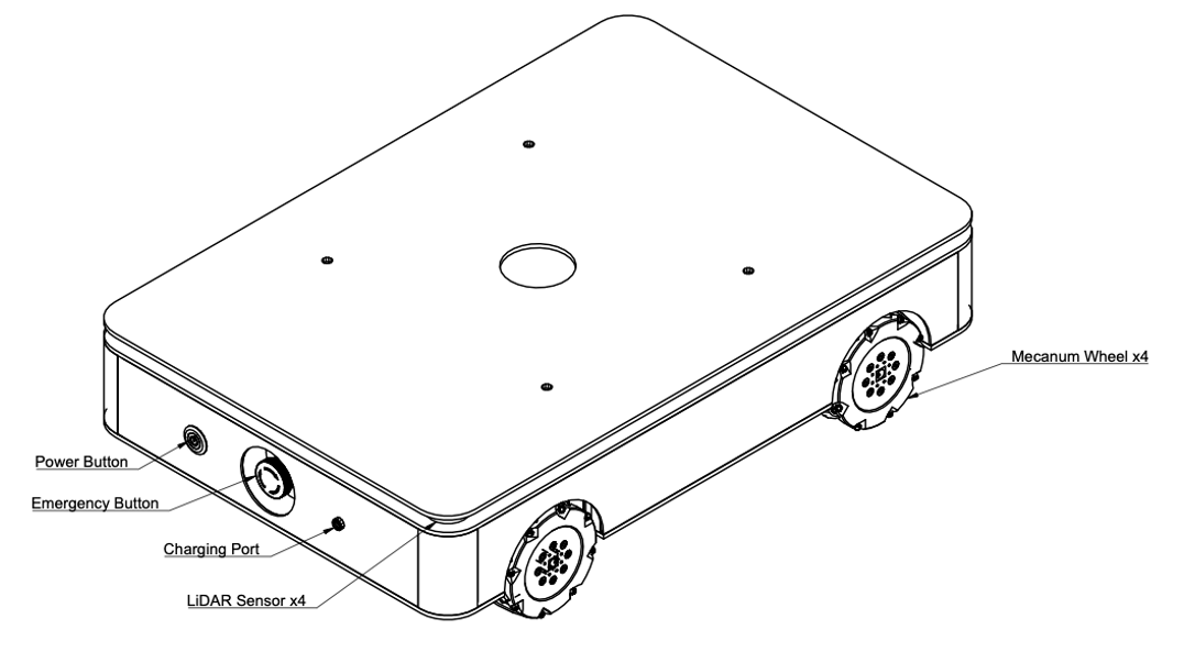
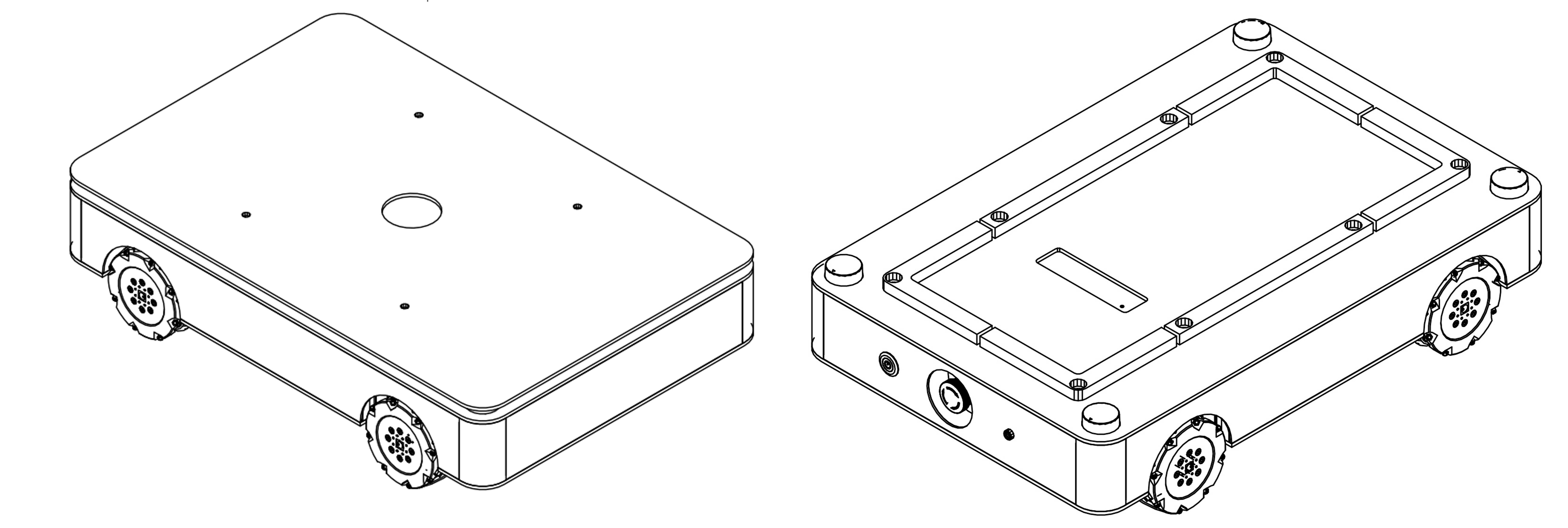
¶ Component Overview
¶ User Interface Overview
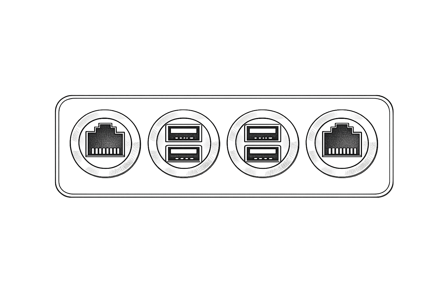
As shown in the figure below, the interface panel is located beneath the robot’s top cover. It includes one Ethernet port on each side and four USB 3.0 ports positioned in the center. The Ethernet ports are intended for network connectivity, while the USB 3.0 ports support high-speed data transfer and external device integration.
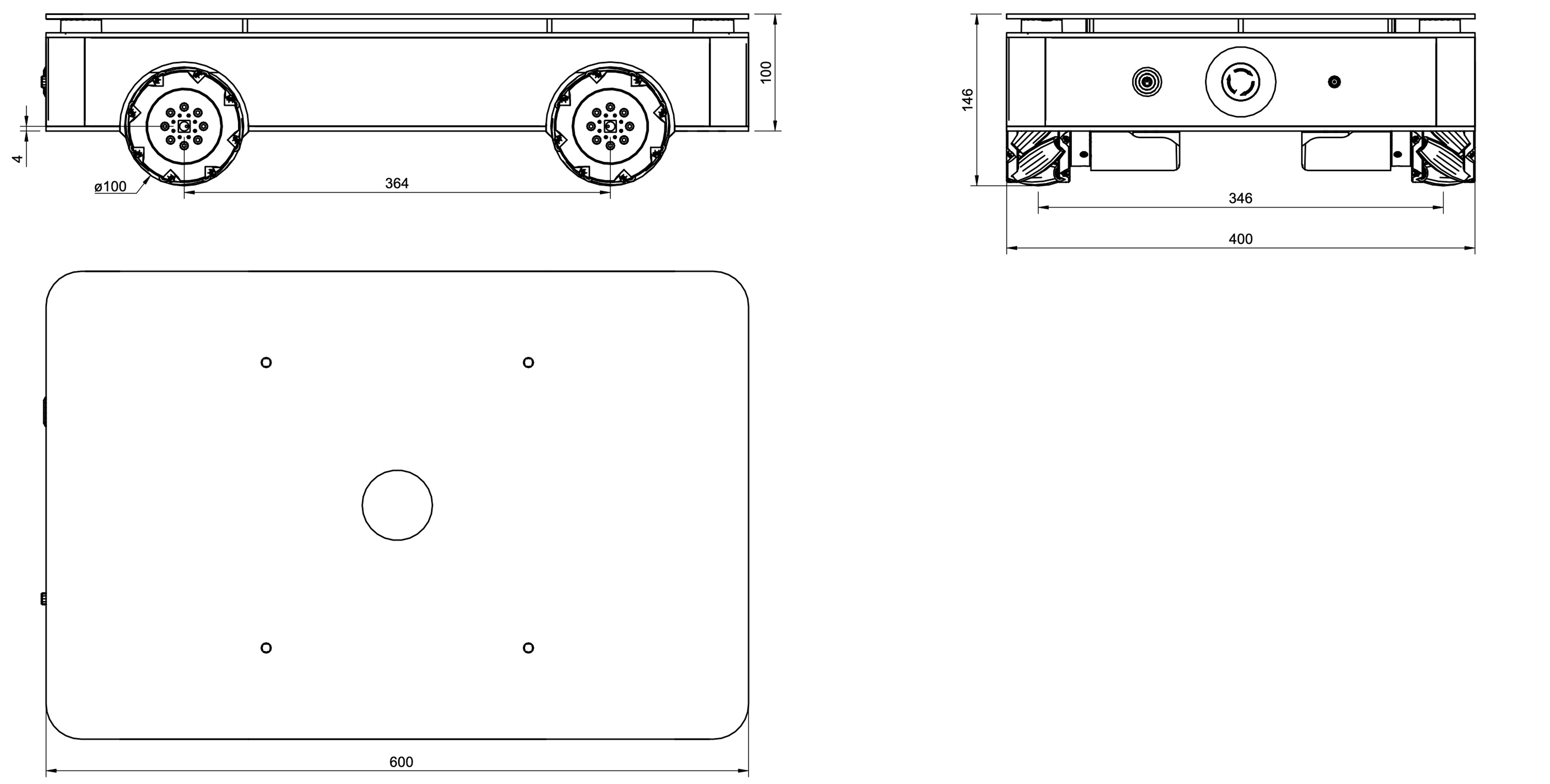
¶ General Dimensions
¶ 6.2 Internal Battery
The robot is powered by a 24 V, 20 Ah LiFePO₄ (Lithium Iron Phosphate) battery pack, providing stable output performance and enhanced operational safety. A dedicated charger is supplied with the system to ensure proper and reliable charging.
To charge the robot, follow the procedure below:
- Ensure that the charger input voltage is set correctly according to the local mains supply (110 VAC or 220–230 VAC), in accordance with the charger specifications.
- Connect the AC power cord to a wall outlet.
- Remove the protective cap from the robot’s charging port.
- Connect the DC charging cable to the robot’s charging port. Charging will begin automatically once connected.
- The charging status is indicated by the LED on the charger (not on the robot):
- Red LED indicates that the battery is charging.
- Green LED indicates that the battery is fully charged. - Before operating the robot, disconnect the charging cable and reinstall the protective cap on the charging port.
Info:
Charging is permitted only when the battery temperature is within 45 °C ± 3 °C. If the battery is depleted and charging does not initiate, ensure that the system has cooled to within the allowable temperature range before retrying.
Charger operating temperature: 0 °C to 40 °C.
Info:
The robot must be charged exclusively with the supplied charger. The use of unauthorized chargers may cause equipment damage or safety hazards. In the event of charger damage or failure, contact the manufacturer or an authorized service center immediately.
¶ 6.3 Mechanical integration
The robot platform provides multiple additional mounting points at various locations on the chassis to support mechanical integration and customization. These mounting interfaces allow users to install auxiliary equipment according to specific application requirements.
Typical examples include brackets for securing transport boxes, display units, or articulated robotic arms. The distributed mounting structure enables flexible expansion while maintaining system stability and structural integrity.
- When the top cover is installed, external components can be mounted directly onto the cover using the pre-drilled M7 threaded holes. These mounting points allow secure attachment of various metal brackets and structural elements, such as standard 30 × 30 mm aluminum extrusion profiles.
- Alternatively, when the top cover is removed, components may be mounted directly onto the robot chassis, providing additional flexibility for structural integration and customized mechanical configurations.
Info:
- When installing additional structures or accessories, carefully consider the robot’s center of gravity. Improper weight distribution may affect stability and could lead to tipping during motion. If necessary, reduce the motor torque or limit the maximum speed to ensure safe operation.
- Added structures may extend beyond the original dimensions of the robot chassis. Such extensions can interfere with the obstacle detection system and may reduce overall obstacle avoidance performance.
- The sensor scanning plane remains fixed at its original mounting height. Obstacles located above or below this scanning plane may not be reliably detected. Before operating the robot, ensure that the working environment is suitable for safe navigation. If required, consider installing the Olive-recommended 3D scanning LiDAR to enhance obstacle detection capability.
- When removing the top cover, take special care not to obstruct the LiDAR sensors or their scanning windows. After the protective cover is removed, the sensors are more exposed; avoid impacts, contamination, or physical damage to ensure reliable operation.
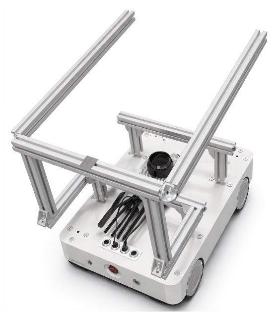
As shown in the example below, the ANT1 platform allows flexible integration of additional modules and structures, enabling a wide range of customized configurations to meet specific application needs.